Fabricated Pinball Streaming Rig

Since the start of the pandemic, I’ve really been enjoying streaming pinball on Twitch (see previous post), but one thing that hasn’t been fun is moving machines around to make room for the mic stands I was using to hold the cameras. They take up a good amount of space and in order to switch from game to game I was invariably having to move machines around to make space.

Inspired by the camera rigs I’ve seen used in tournaments, I decided to make my own. The beauty of them is just how compact they are – they are almost the same width as a machine and (because they are on wheels) they can be slid from game to game with the machines pretty much right up against each other. Instead of using aluminum extrusions, though, I decided to try making mine out of wood – mostly because that’s what I had on hand already, and plywood is relatively inexpensive.

I started with a quarter sheet of plywood (2′ x 4′ x 1/2″) and off to my backyard wood shop I went!

I started by making repeated cuts lengthwise, making 2″ wide strips.

Plywood often has a slight bow to it, but you can make a straighter and stronger piece by laminating two pieces together, flipping one relative to the other so the bows are in the opposite direction. They sort of cancel each other out and you end up with a straighter piece. They won’t be perfect but it was plenty good for this purpose.

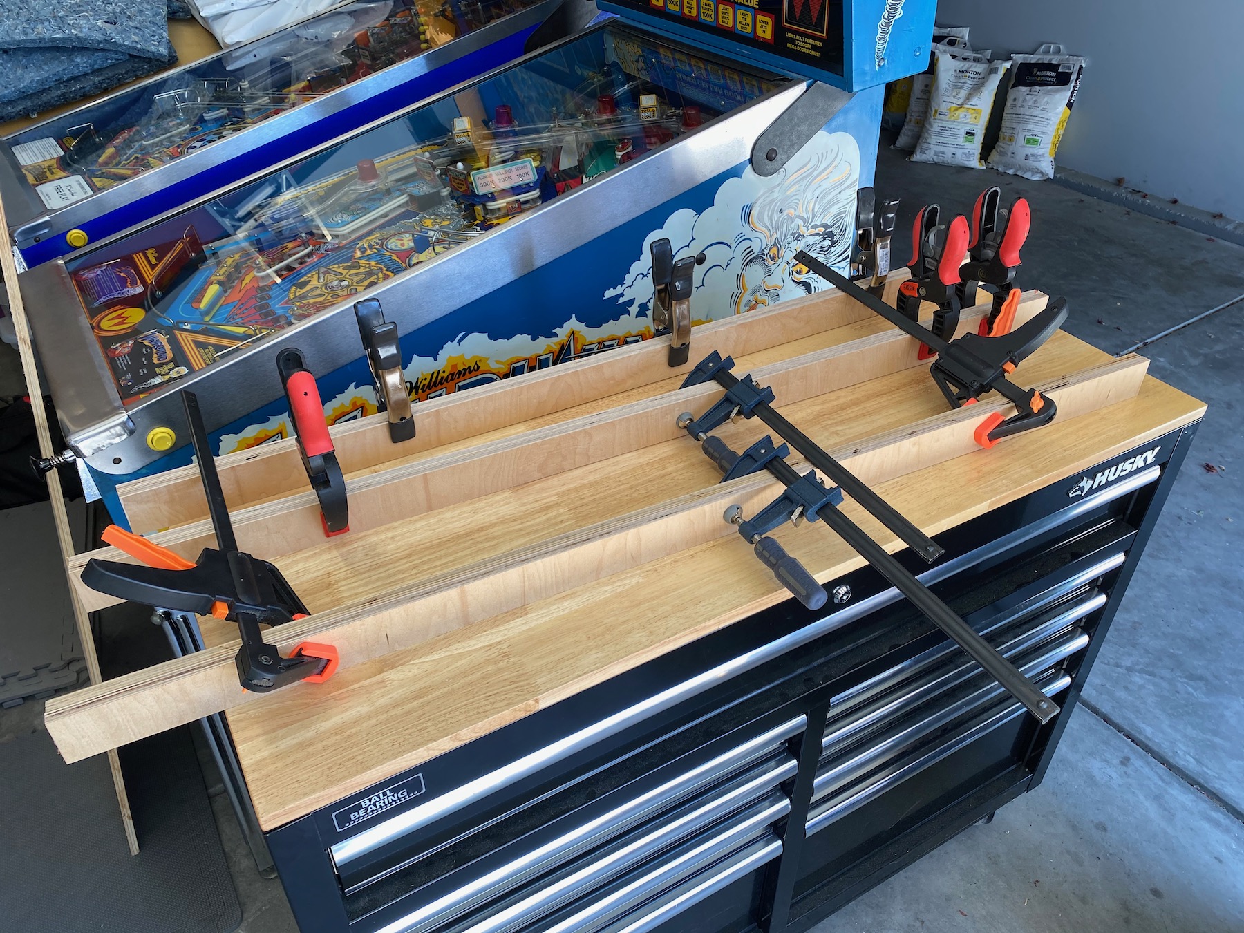
These laminated pieces are the basis of every part of my rig – the legs which have casters at each end, the uprights, and the cross piece at the top. Here are all the pieces of the puzzle.

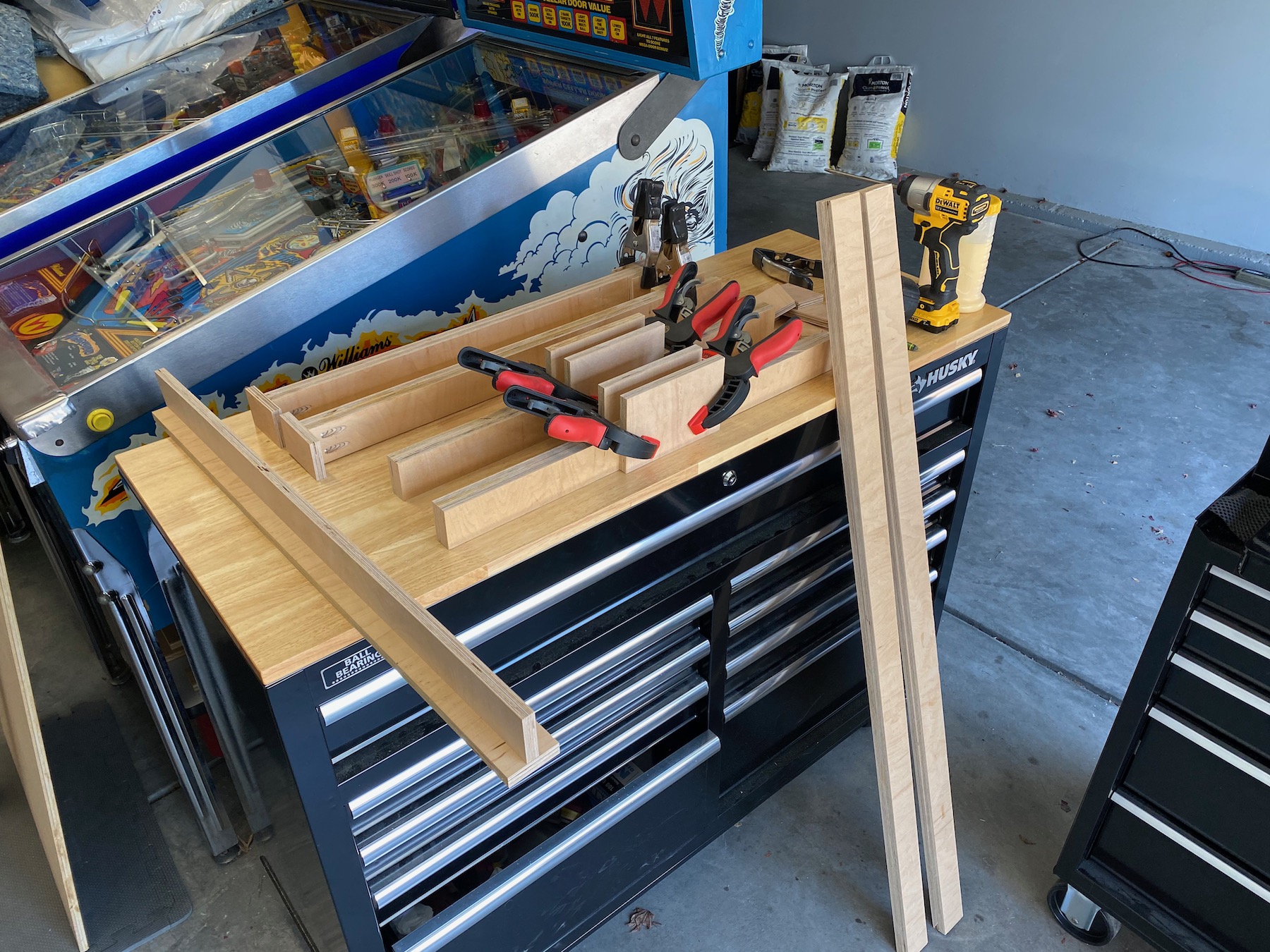
Because my longest piece is only 48″ which isn’t tall enough for the rig, I ended up using small strips to form a U joint. Each individual piece of my design shown below is primarily glued together, with a few pocket screws in some of pieces. The pieces are then assembled into the final rig with only nuts and bolts, making breakdown easy for storage or transportation. Here are the main components ready to go!

And then together for the first time! It looks like this should work! All done with about a quarter sheet of plywood which I already had left over from another project – this was a very cheap project to put together.

I couldn’t stop there though and decided to build a mobile computer rig for my old computer re-purposed for streaming. I bought two of the cheapest 20″ monitor I could find online, a dual monitor mount, and put it together – it’s also on casters for easy moving from game to game. Having two monitors allows me to monitor both the streaming software and the Twitch dashboard simultaneously and is a huge upgrade over the laptop I was using sitting on a stool before.

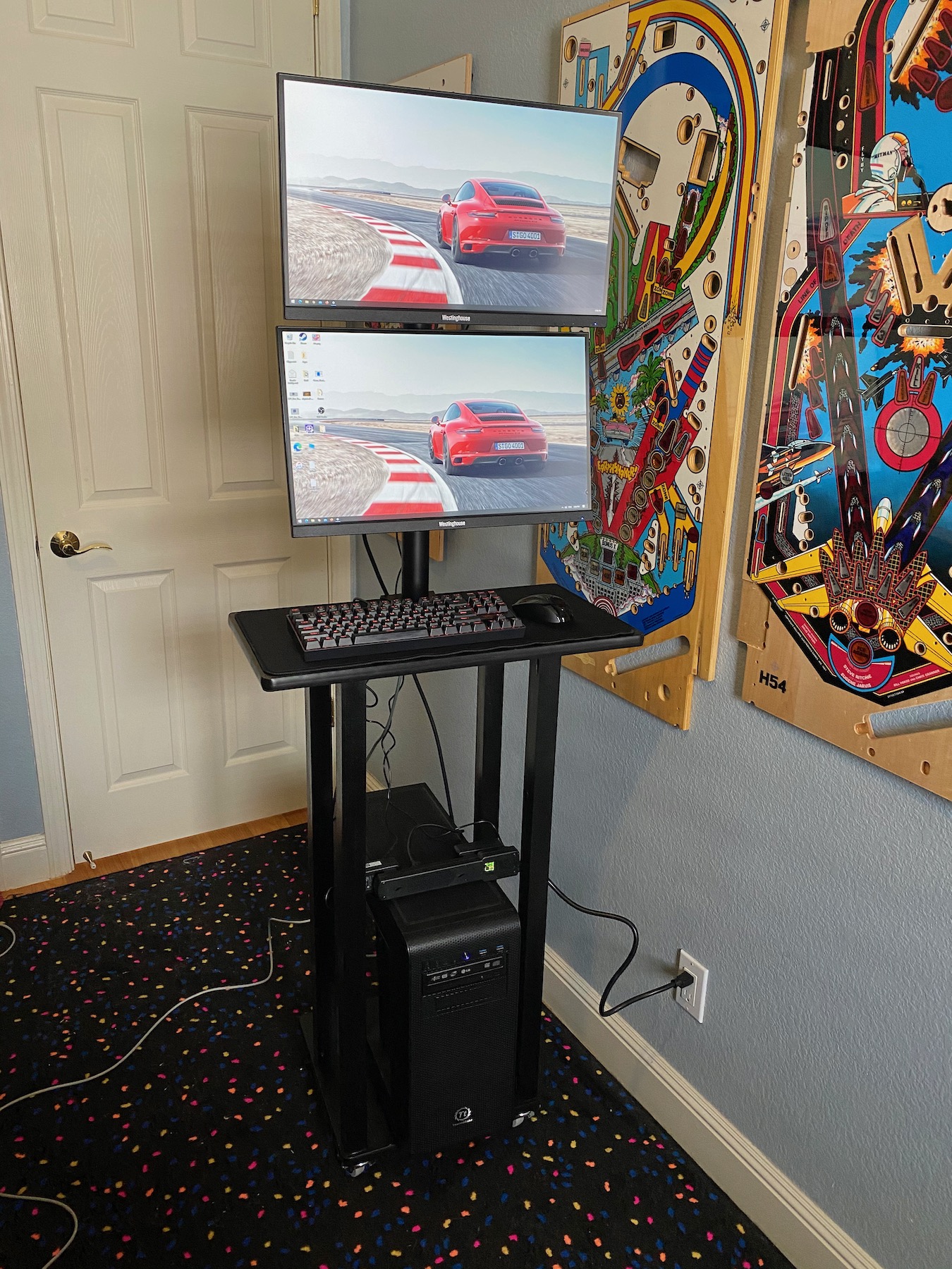
One more upgrade worth mentioning – 802.11ax AKA WiFi 6! I put a new wireless card in my PC which allows me plenty of bandwidth for wirelessly streaming from the garage instead of having to run a long ethernet cable across the driveway 🙂 It’s kind of incredible the speeds you can get over WiFi now – speeds that were only possible with a wire only a short time ago. 

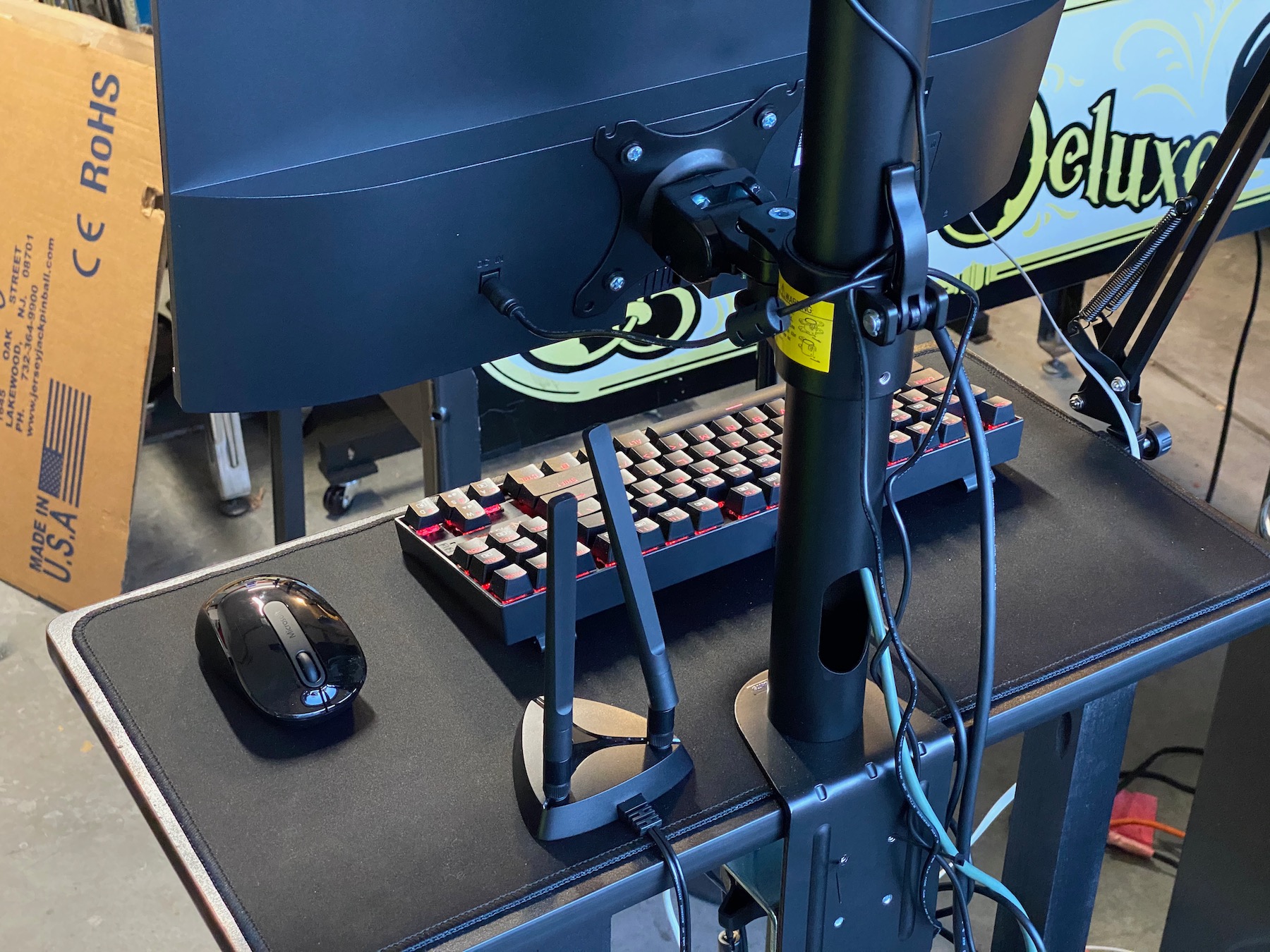
A coat of black paint on the streaming rig and it is all done! Tune in to catch the show at https://twitch.tv/abpinball!

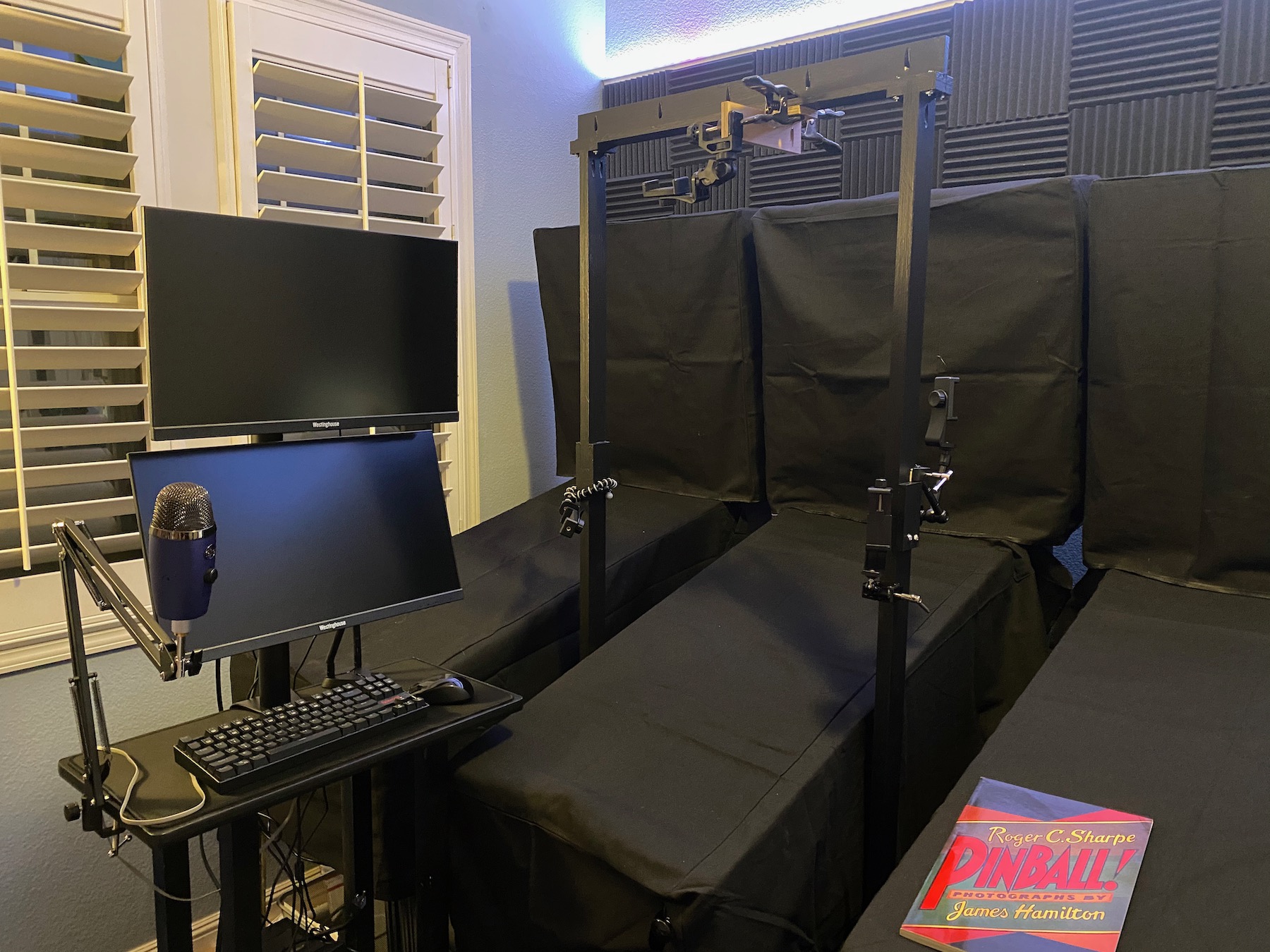
Here is the cut list and dimensions in case you want to make one yourself.

  1. Make 10 strips, 2″ x 48″ x 1/2″
  2. Laminate 8 of the above pieces into pairs, forming 4 separate laminations
  3. The remaining 2 strips should be cut to 30″ wide and assembled at a 90 degree angle – this will be the top cross piece.
  4. Cut 2 of the laminations in half crosswise, forming pieces 2″ x 24″ x 1″. Two of these will be the legs and two will be the upright extensions. The remaining two laminations (2″ x 48″ x 1″) are the main uprights
  5. Use scraps to make the U joints / caster supports / etc, assemble and enjoy!

Important Note: I made mine 30″ wide and while I’m happy with that, I do have to stretch the uprights outwards a bit to clear the legs of the machine on the way in and out. There is plenty of flex to do this and I’m happy with my dimension, but be aware and adjust as necessary for your needs. Another inch width probably wouldn’t hurt.


Posted in Uncategorized | Tagged , | Leave a comment

See Alpha Bravo Pinball live on Twitch!

Hi!

The world has changed over the last several weeks, and at least for now pinball nights with friends are a thing of the past. As an experiment and to try to get some human interaction in my pinball playing, I started streaming on Twitch. I’m very pleased with it so far – while not the same as playing with friends, having folks follow along on the stream and interact via chat is a fun thing for sure and adds a certain amount of pressure to play well that can be easy to miss when you’re just playing alone.

If you’d like to join in, head on over to my channel on Twitch. Hope to see you there! And if you’ve thought about streaming yourself, I highly recommend it! I got a lot of good advice on setting up my stream from Deadflip’s guide.

Posted in Uncategorized | 1 Comment

Arcade “Superbench” Part 2 of 2 – Final Assembly

After finishing the blue paint (see part 1), my Superbench cabinet was now ready for final assembly with artwork, sound and electronics.

The first part I installed is the power connector to the back of the cabinet. This nice unit has built-in fuse protection as well as a power switch in addition to the IEC connector. Definitely gives the cabinet a more professional look vs a power cable dangling out the back!

Next up, parts for the front! I installed the speaker panel vinyl graphics I had printed with Escape Pod Online and it turned out great. They were printed on really nice material which made installation easy without any bubbles. The woofer and the DIN-15 connector panel for the controllers went on next. Looking good!

Speaking of the controllers though, here’s how I tackled those. I started with two identical MadCatz TE sticks bought on Craiglists – they’re nice enough quality controllers built with arcade-grade Sanwa components. They were originally of the PS3/XBox 360 era and connected over USB, but that mattered little since I wasn’t going to re-use their electronics. Instead, I chopped all of it out and wired each switch directly to individual wires of a DIN-15 cable (hence the DIN-15 connector panel on the cabinet).

Before:

After:

This approach wires every switch exactly as it would be on a 90’s-era arcade cabinet.

Back to the Superbench though, I continued along with the two 4-inch speakers and the coin door. Here’s a shot showing the inside – you can see the power supply and the speaker amp is also now in place.

The inside is getting near completion at this point, but there is still one more board to mount – the JROK video encoder I’m using to transform the RGB output from the arcade board to Component Video my TV takes. One of the nice things of this type of video transformation is that it adds zero delay – that’s good because otherwise it would defeat one of the main purposes of playing on a CRT! Here is the right side with all components installed. Note the volume controls are close to the coin door and hence easily accessed from the front of the cabinet.

At this point the front and interior are pretty much done! Still more to do, though – at this point it was safe to install the top panel of the cabinet since no more wiring was needed (as seen below) and the casters on the bottom:

And finally to complete the back, exhaust fans and grills, and a door.

This is also when I installed the T-molding. It was more work than I was expecting to hammer it in, but it turned out pretty good!

Last but not least the side art! I first put down some tape guides in order to be 100% sure they were centered and level.

And the final result with a sheet of tempered glass on top!

Very happy with the final product. At this point I gave the spray paint a few more days to fully cure before putting a heavy CRT on it, and in the meantime fabricated a vertical mount for my CPS-2 board.

The CPS-3 board can stay horizontal as it’s quite a bit smaller. Finally it was time to get the Superbench into my game room and connect it all together with the JAMMA harness – powered it up and it all works great! An excellent addition to the pinball machines.

Posted in Uncategorized | Leave a comment

Arcade “Superbench” Part 1 of 2 – Design and Construction

I recently bought an old 20″ CRT television for retro gaming – nothing beats the authentic feel of it for playing old games, plus (unlike many modern screens) it is lag-free! I thought it could be also a neat way to play my Capcom CPS arcade boards as those also feel much more “right” on a CRT, too, and I have no desire to have a bulky full-size video arcade cabinet in my house.

The typical term for a device that connects arcade boards to a television (and hence lets you play the game outside of a big cabinet) is a “supergun”. They provide a video output suitable for a TV, as well as sound and controller ports, and finally they a power supply to power the arcade board. While I could certainly go this route myself, I don’t have a TV bench for my new (old) TV, so I thought it would be neat to design a combination Supergun + TV bench – hence the idea of the Superbench was born! Some key ideas that I thought would be interesting for it are:

  • Functions primarily as a TV bench but with a design inspired by a real video arcade cabinet
  • Include a built-in sound system with speakers and an amp which will sound much better than the crummy CRT TV speakers
  • Include all other hookups necessary to play Capcom CPS arcade boards – power, video, etc.

So, I started toying around with some ideas in a CAD program. I’d never used Fusion 360 before, but hey, it’s free for hobby use, so why not? The learning curve was slightly steep as it is a pretty powerful tool, but with limitless amounts of inforomation online it seems like you can learn anything these days. Here was my first pass at putting down in CAD what I had in my head:

A simple box with two small full-range speakers, a bigger woofer for bass, a coin door, and casters to make it easy to move around (CRTs are heavy!). It is really cool how you can visualize and tweak the design so easily in CAD before you ever touch a single piece of material! I played around with a few changes but in the end my final design was pretty close to the above, with the only major change being removing the top part of the front face and changing it from three pieces to two. I decided to model my color scheme on the Capcom Big Blue arcade cabinet – here is the final design render:

Note the addition of a twin DB-15 connector panel at the bottom left. This will let me attach two controllers, but that topic deserves its own post!

So, off to the fancy wood store to buy some material. MDF would be appropriate and has a super even finish for painting, but it is quite heavy and can sag. Plywood would work too and has a great strength to weight ratio, but it is harder to paint without leaving visible wood grain patterns which I didn’t want for this design. I found a product at my local hardwood supply store called Jaycore (in 3/4 inch thickness) which appears to be the best of both worlds – it has a plywood core with MDF faces. Much lighter than MDF, with nice smooth faces and the strength of plywood! Perfect! I calculated I only needed one four-foot by eight-foot sheet for the whole project. Here it is in my driveway ready for the first cut. I used a straight edge and a circular saw as the sheet is WAY too big to handle on my small table saw. Steve Ramsey’s tips came in handy here – his technique of cutting on top of some insulation worked great! Thanks Steve!

That got me down to manageable-size pieces I could cut using my small table saw. As my driveway is my wood shop, my tools need to be small enough to be portable – they are stored under pinball machines when not in use! 🤣

The main box structure of the cabinet will be assembled using wood glue, dowels and pocket screws. I used an inexpensive dowel jig to drill holes into the edges of the boards:

Next I used my router to carve out a recess for the power switch face plate on the right side piece:

I also used the router to cut the groove on the edge of the boards that will get T-molding. Here is a test piece done to dial in the position of the groove, with a small strip of the gray T-molding I will use installed:

In the photo above you can clearly see the different layers of the Jaycore, with plywood in the middle and MDF on both faces.

With the top, bottom, left and right pieces done, I then cut a smaller panel for the back that will have two exhaust fans – something like this:

They’re simply 120mm computer case fans but work well for other random application such as this one and are really quiet.

I then used a circle cutting jig on the router to cut the openings for the fans:

I now had enough pieces to assemble the basic box shape! I drilled pocket holes (not pictured) and put it together. It turned out pretty square and everything lined up well. Woo! I’m sure the experienced woodworkers are rolling their eyes here but this is the biggest woodworking project I’ve ever undertaken so forgive me while I pat myself on the back 😛

Also note my pocket holes are on the inside, pointed towards the outside – not as strong as the other way around. Some (Hi again Steve!) may consider it a no-no, but I did a test piece and given I’m also using dowels the joint ended up being plenty strong. Doing it this way saved me a ton of work filling the pockets that would be visible if I had done them on the outside.

On to the front! I used a jigsaw for the coin door and DB-15 cutouts, and the woofer hole was cut in a similar fashion to the fan holes.

I then created the top speaker panel. It’s construction was very similar to the fan panel, except two of the edges were beveled 15° – this was my first time using the bevel feature on my table saw! A few pocket holes and a reinforcing piece between the two and voilà, my box has a front now.

Although most of the interior wiring and kitting out will be done after paint, I decided to do the 120V now to avoid damaging the finish later. My cabinet is wired with two separate 120V circuits via a dual switch, such that I can turn on and off the power to the sound system and arcade boards separately. This makes it possible to use the Superbench as a sound system only, useful for playing game consoles.

You’ll also notice the small cutout between the two fan holes – this is to allow the passage of video cables from inside the bench up to the TV.

Finally, on to paint! If you’ve never painted MDF before, you’ll find that it soaks up paint like a sponge – this makes it very very difficult to get a good finish. I did some research online and found a product called Zinnser BIN which is supposed to seal the MDF, leading to much better results. I did a small test piece first and it seemed to work, so off I went!

My back yard is not just my wood shop – it’s my spray booth, too! 😬 Dust can be a real problem painting outdoors like this but I’ve found as long as it’s not too windy and the surfaces are all vertical you can still get good results – forget about it with horizontal pieces though, the wet paint will catch every little piece of dust falling from the air. Notice the top piece isn’t on in the photo above and will be painted separately.

A few coats of Zinnser BIN done, with the top piece leaning on the fence in the background. I then sanded it very lightly to smooth out the finish, and moved on to paint. I used “Gloss Deep Blue” by Rustoleum Painter’s Touch 2x. The finish came out pretty nice! Note I didn’t have to worry about the edges of the boards as those will be covered in plastic T-molding.

That’s it for now! Stay tuned for the exciting conclusion in Part 2 in which I will finish the project out with interior wiring, sound, artwork, and trimmings!

Posted in arcade | Tagged , , , , | 1 Comment