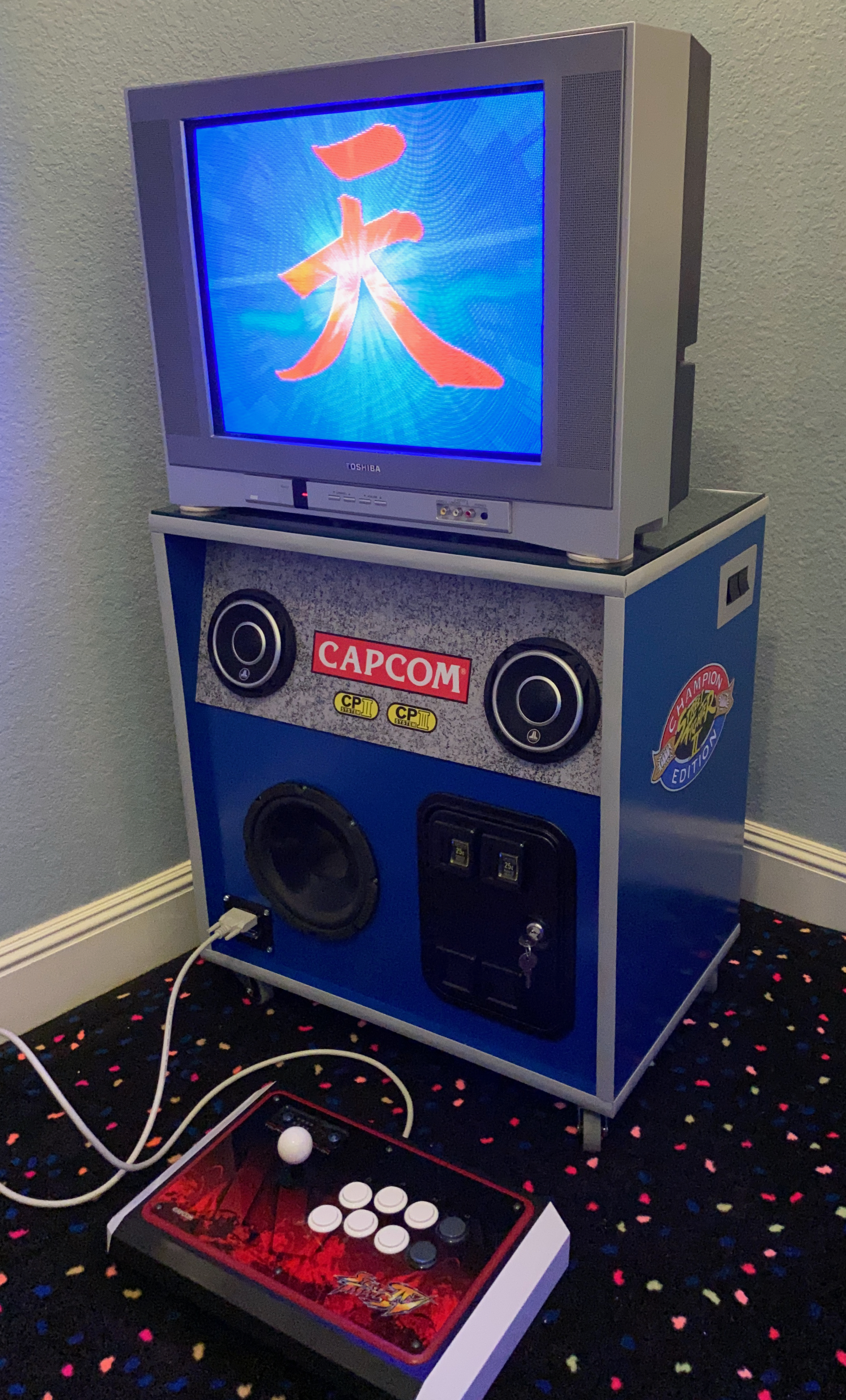
I recently bought an old 20″ CRT television for retro gaming – nothing beats the authentic feel of it for playing old games, plus (unlike many modern screens) it is lag-free! I thought it could be also a neat way to play my Capcom CPS arcade boards as those also feel much more “right” on a CRT, too, and I have no desire to have a bulky full-size video arcade cabinet in my house.
The typical term for a device that connects arcade boards to a television (and hence lets you play the game outside of a big cabinet) is a “supergun”. They provide a video output suitable for a TV, as well as sound and controller ports, and finally they a power supply to power the arcade board. While I could certainly go this route myself, I don’t have a TV bench for my new (old) TV, so I thought it would be neat to design a combination Supergun + TV bench – hence the idea of the Superbench was born! Some key ideas that I thought would be interesting for it are:
- Functions primarily as a TV bench but with a design inspired by a real video arcade cabinet
- Include a built-in sound system with speakers and an amp which will sound much better than the crummy CRT TV speakers
- Include all other hookups necessary to play Capcom CPS arcade boards – power, video, etc.
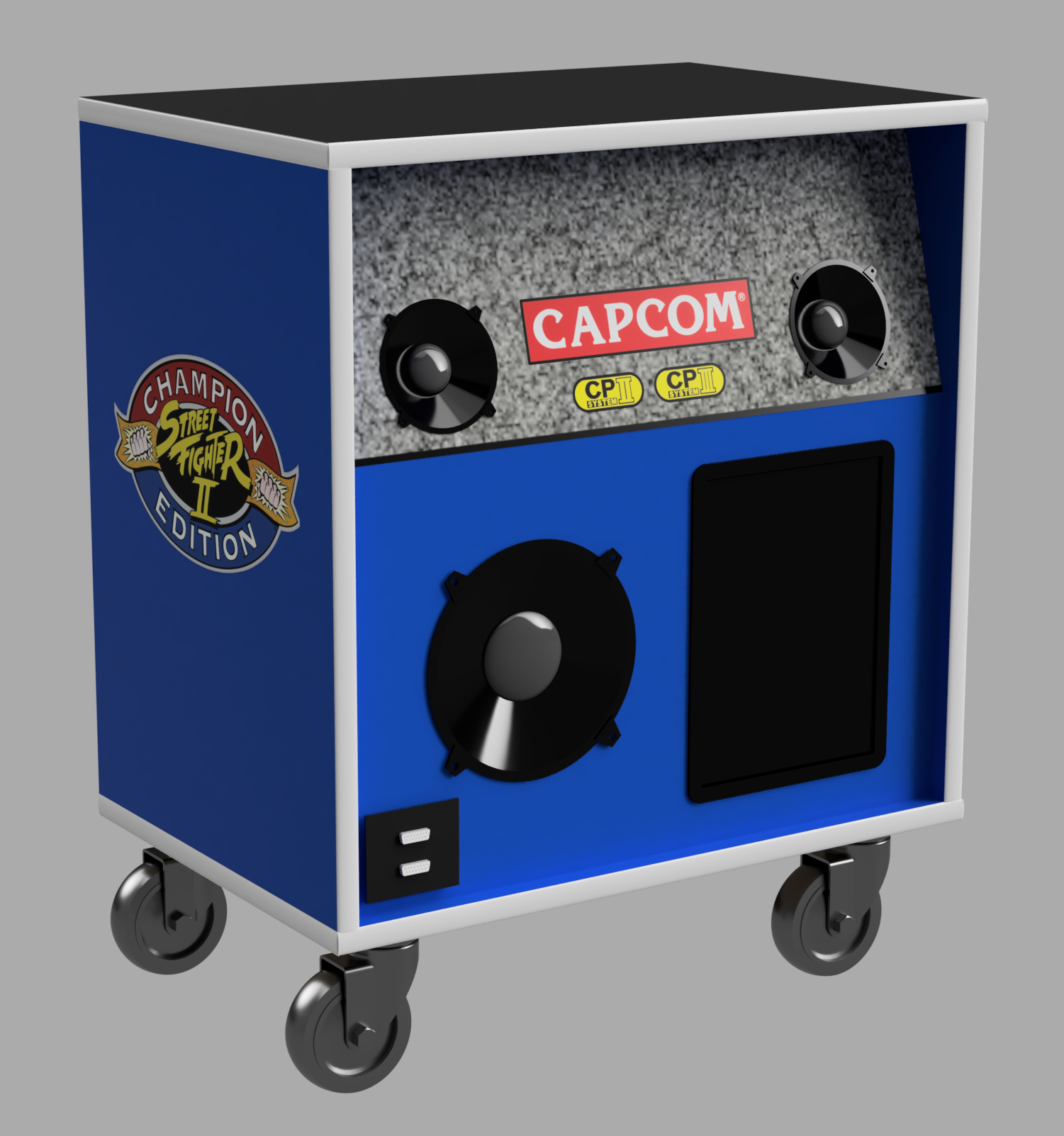
So, I started toying around with some ideas in a CAD program. I’d never used Fusion 360 before, but hey, it’s free for hobby use, so why not? The learning curve was slightly steep as it is a pretty powerful tool, but with limitless amounts of inforomation online it seems like you can learn anything these days. Here was my first pass at putting down in CAD what I had in my head:
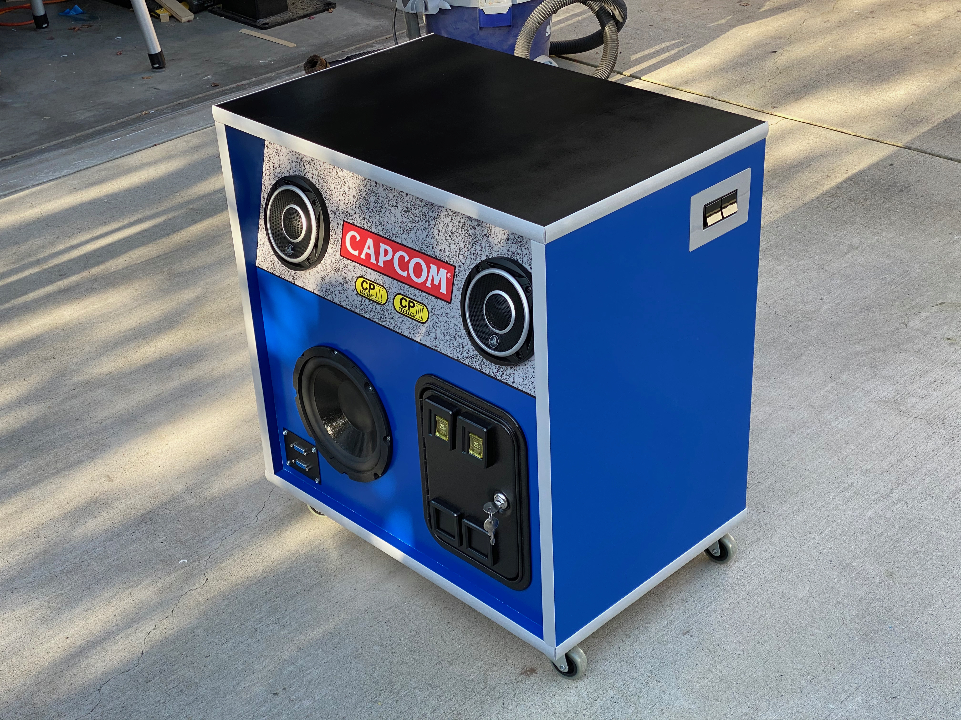
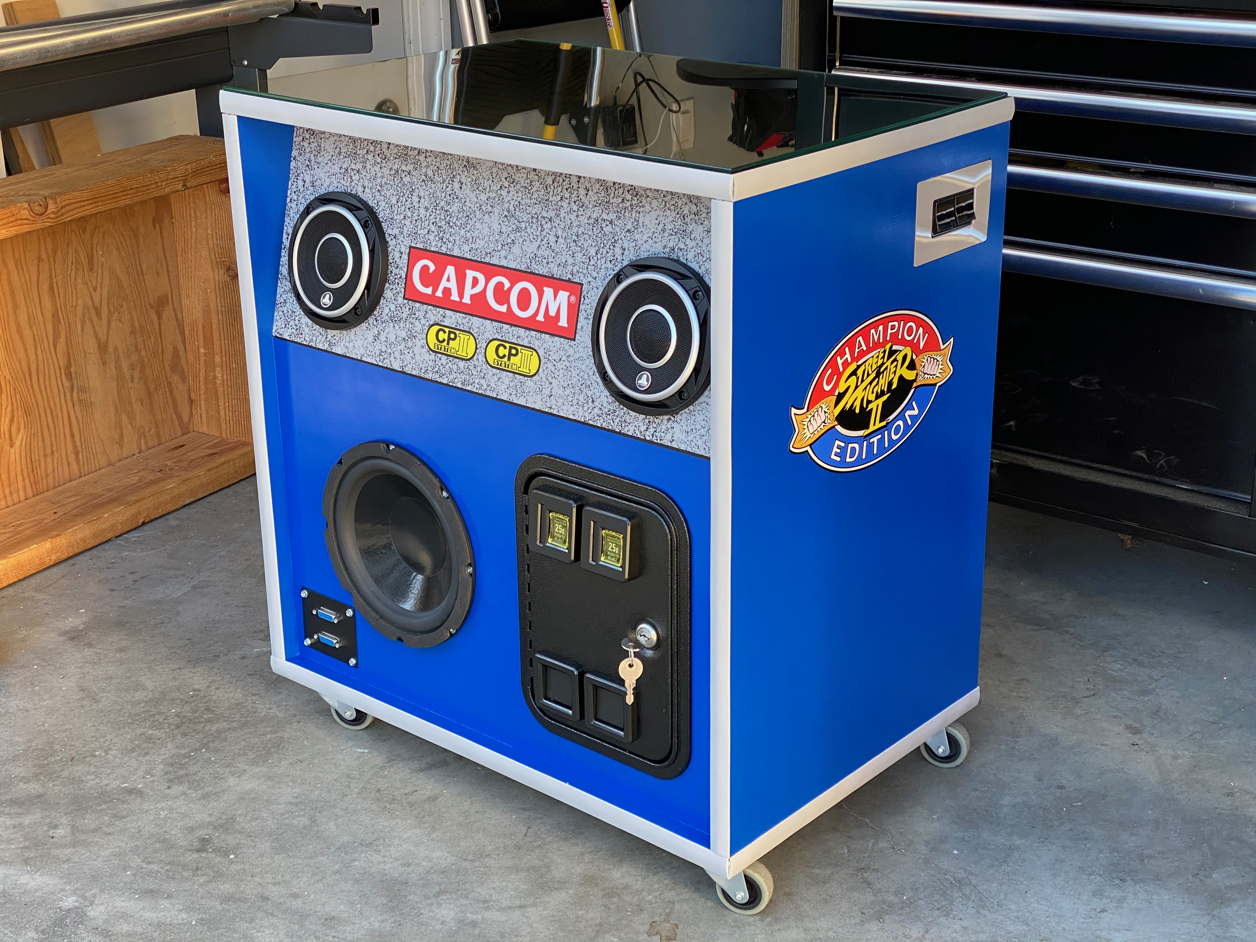
A simple box with two small full-range speakers, a bigger woofer for bass, a coin door, and casters to make it easy to move around (CRTs are heavy!). It is really cool how you can visualize and tweak the design so easily in CAD before you ever touch a single piece of material! I played around with a few changes but in the end my final design was pretty close to the above, with the only major change being removing the top part of the front face and changing it from three pieces to two. I decided to model my color scheme on the Capcom Big Blue arcade cabinet – here is the final design render:
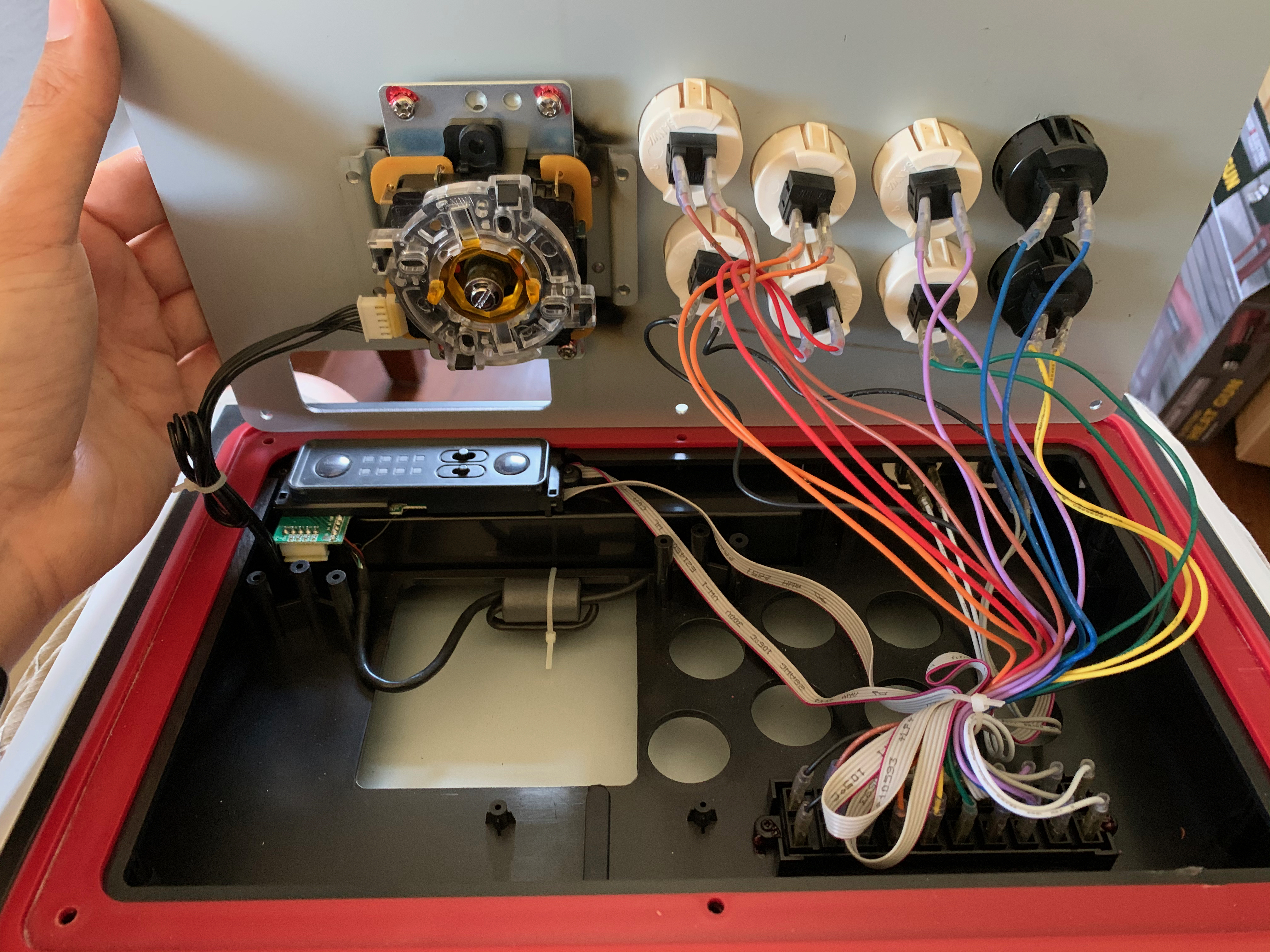
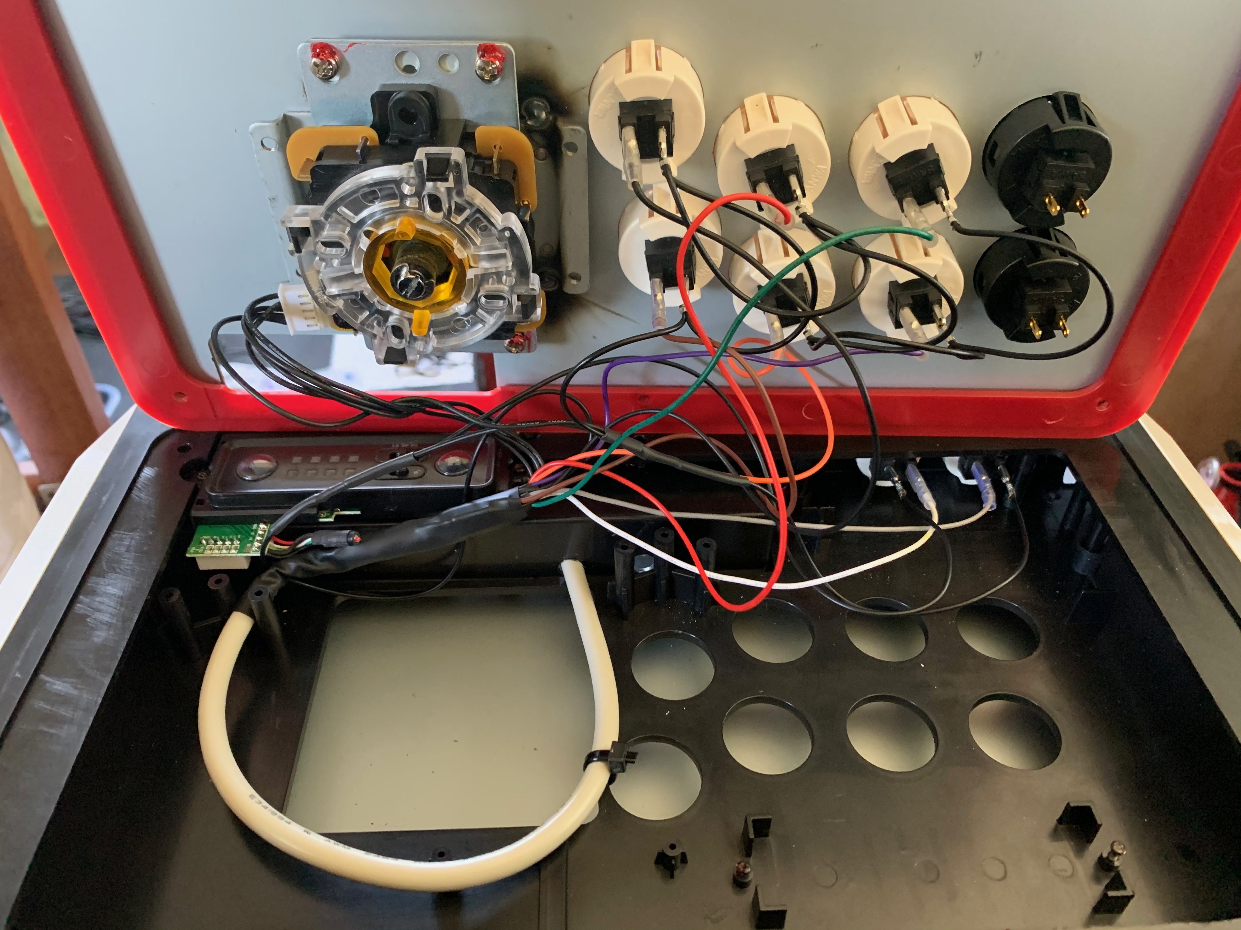
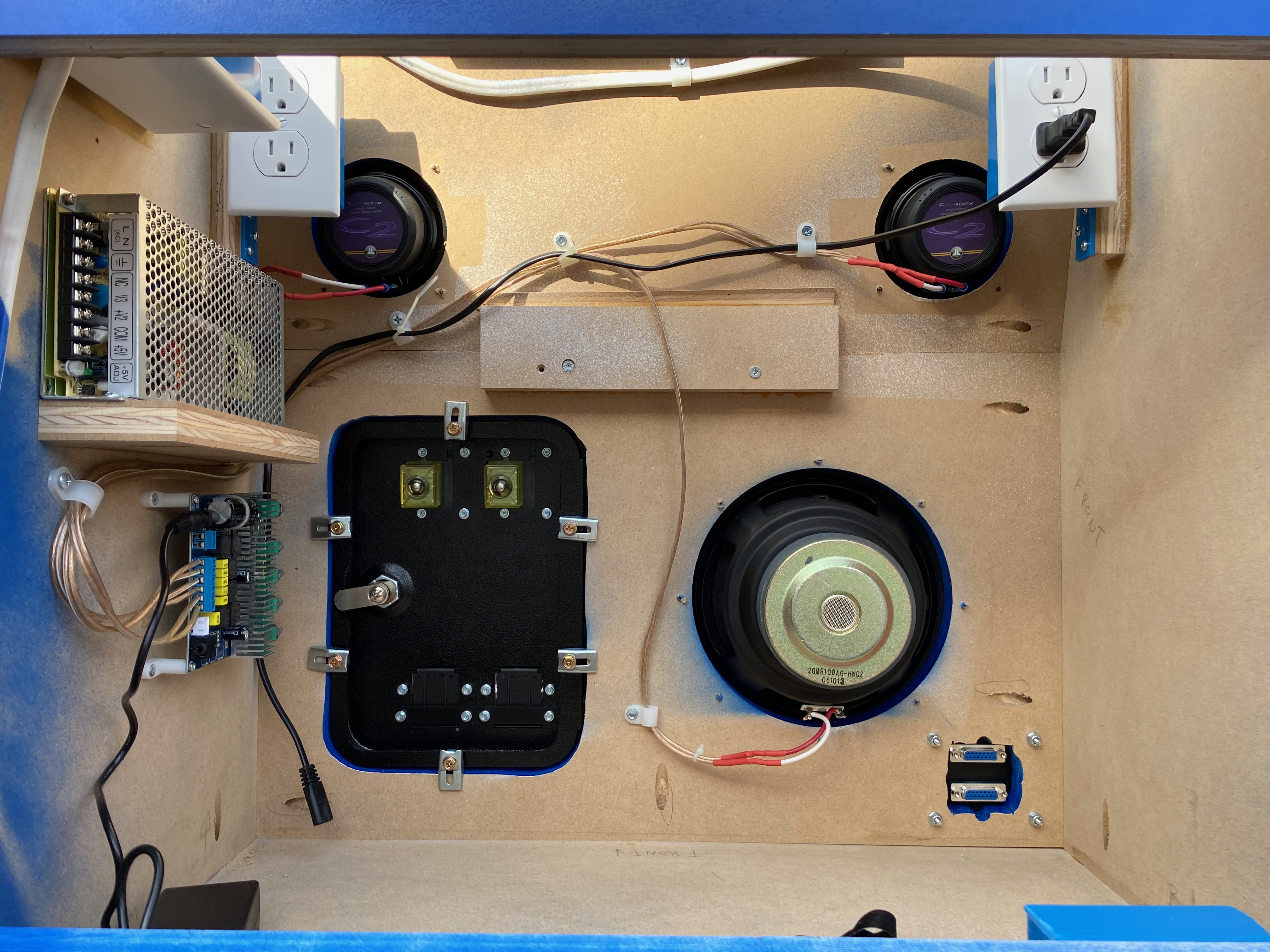
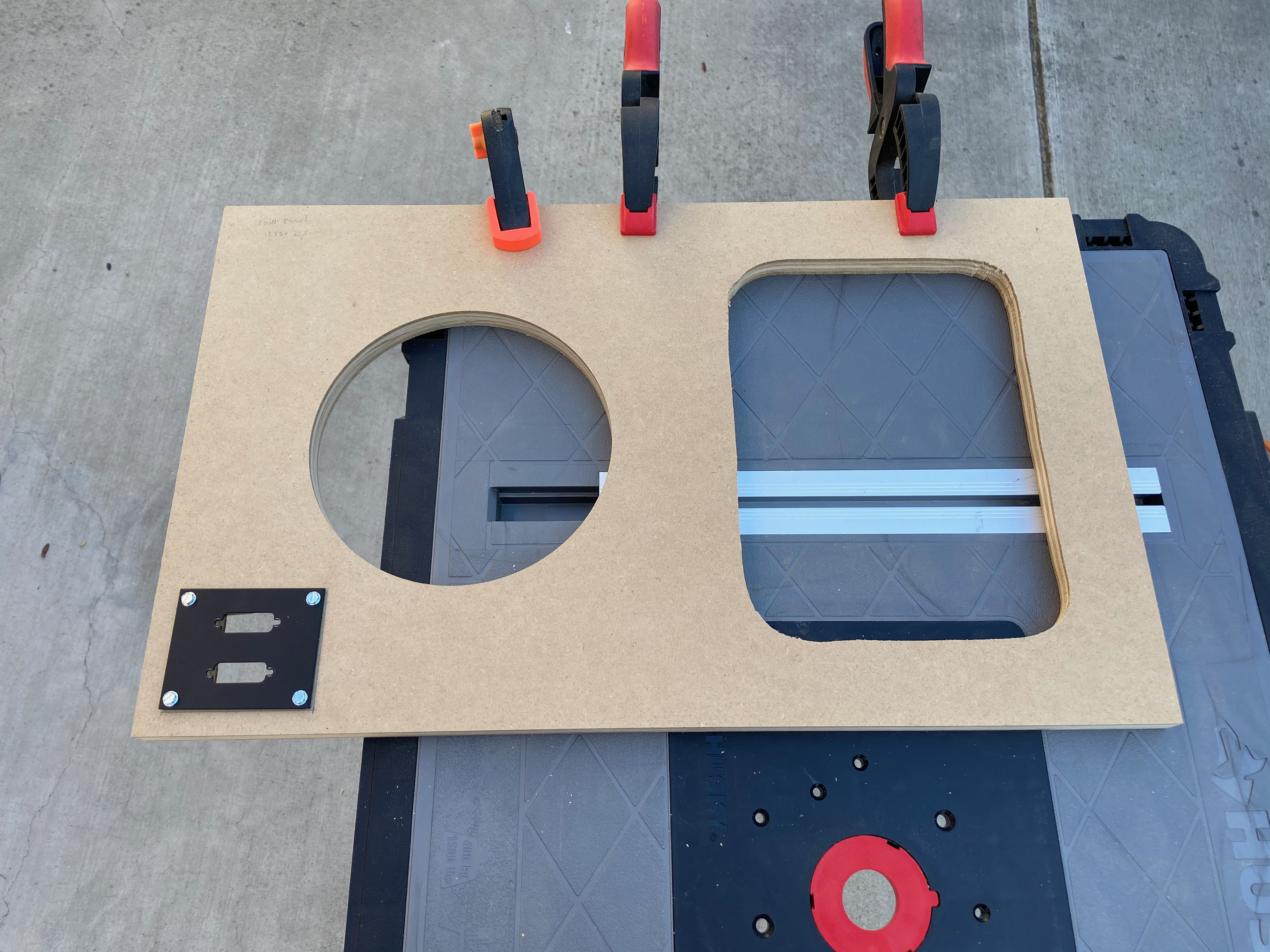
Note the addition of a twin DB-15 connector panel at the bottom left. This will let me attach two controllers, but that topic deserves its own post!
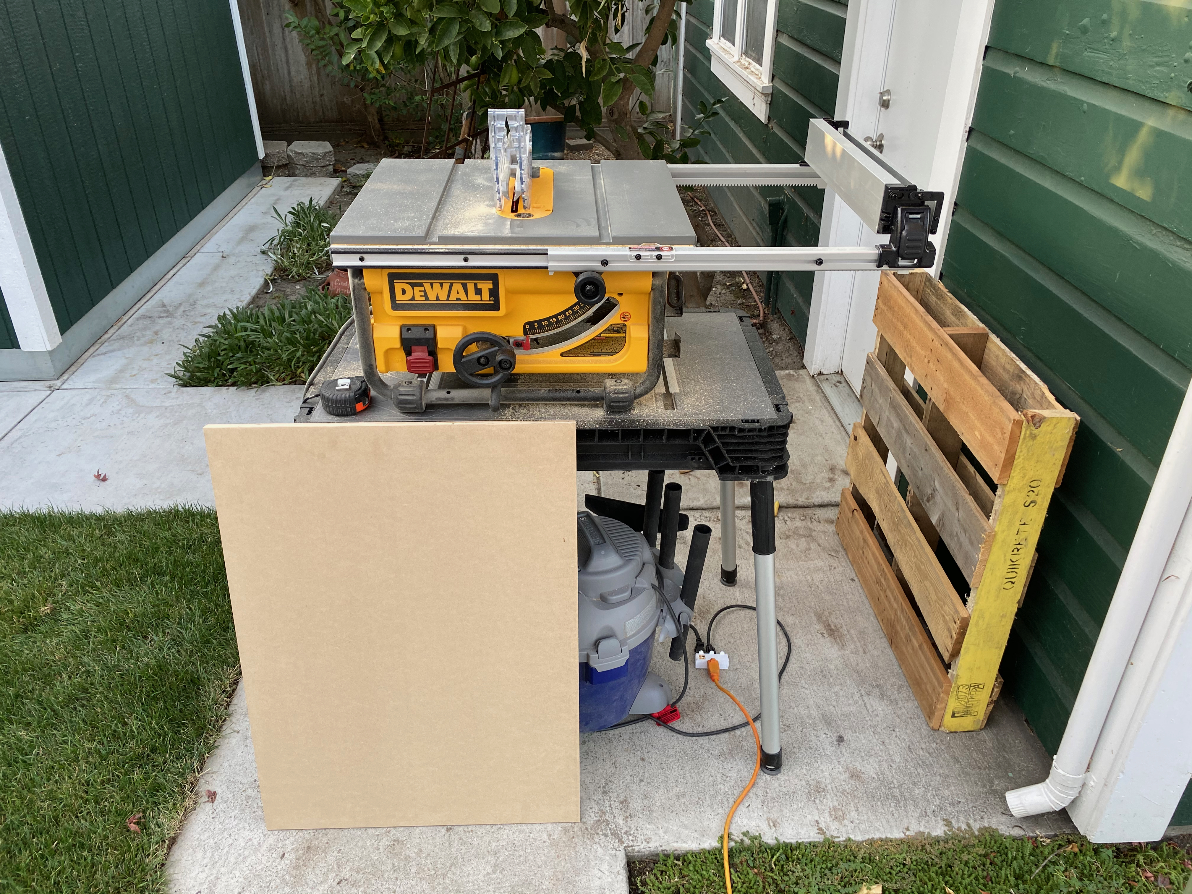
So, off to the fancy wood store to buy some material. MDF would be appropriate and has a super even finish for painting, but it is quite heavy and can sag. Plywood would work too and has a great strength to weight ratio, but it is harder to paint without leaving visible wood grain patterns which I didn’t want for this design. I found a product at my local hardwood supply store called Jaycore (in 3/4 inch thickness) which appears to be the best of both worlds – it has a plywood core with MDF faces. Much lighter than MDF, with nice smooth faces and the strength of plywood! Perfect! I calculated I only needed one four-foot by eight-foot sheet for the whole project. Here it is in my driveway ready for the first cut. I used a straight edge and a circular saw as the sheet is WAY too big to handle on my small table saw. Steve Ramsey’s tips came in handy here – his technique of cutting on top of some insulation worked great! Thanks Steve!
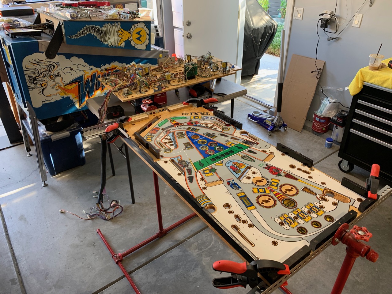
That got me down to manageable-size pieces I could cut using my small table saw. As my driveway is my wood shop, my tools need to be small enough to be portable – they are stored under pinball machines when not in use! 🤣 
The main box structure of the cabinet will be assembled using wood glue, dowels and pocket screws. I used an inexpensive dowel jig to drill holes into the edges of the boards:
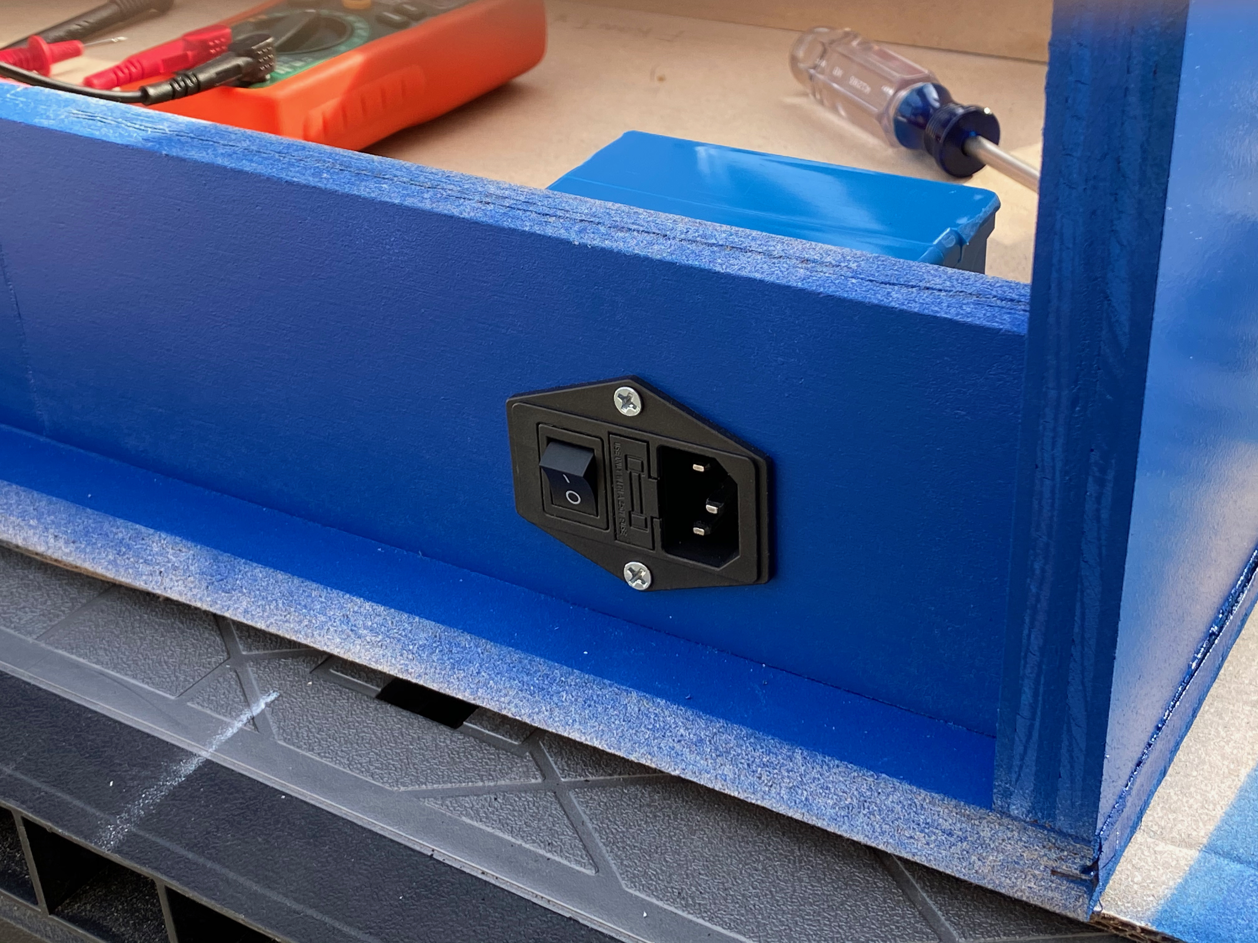
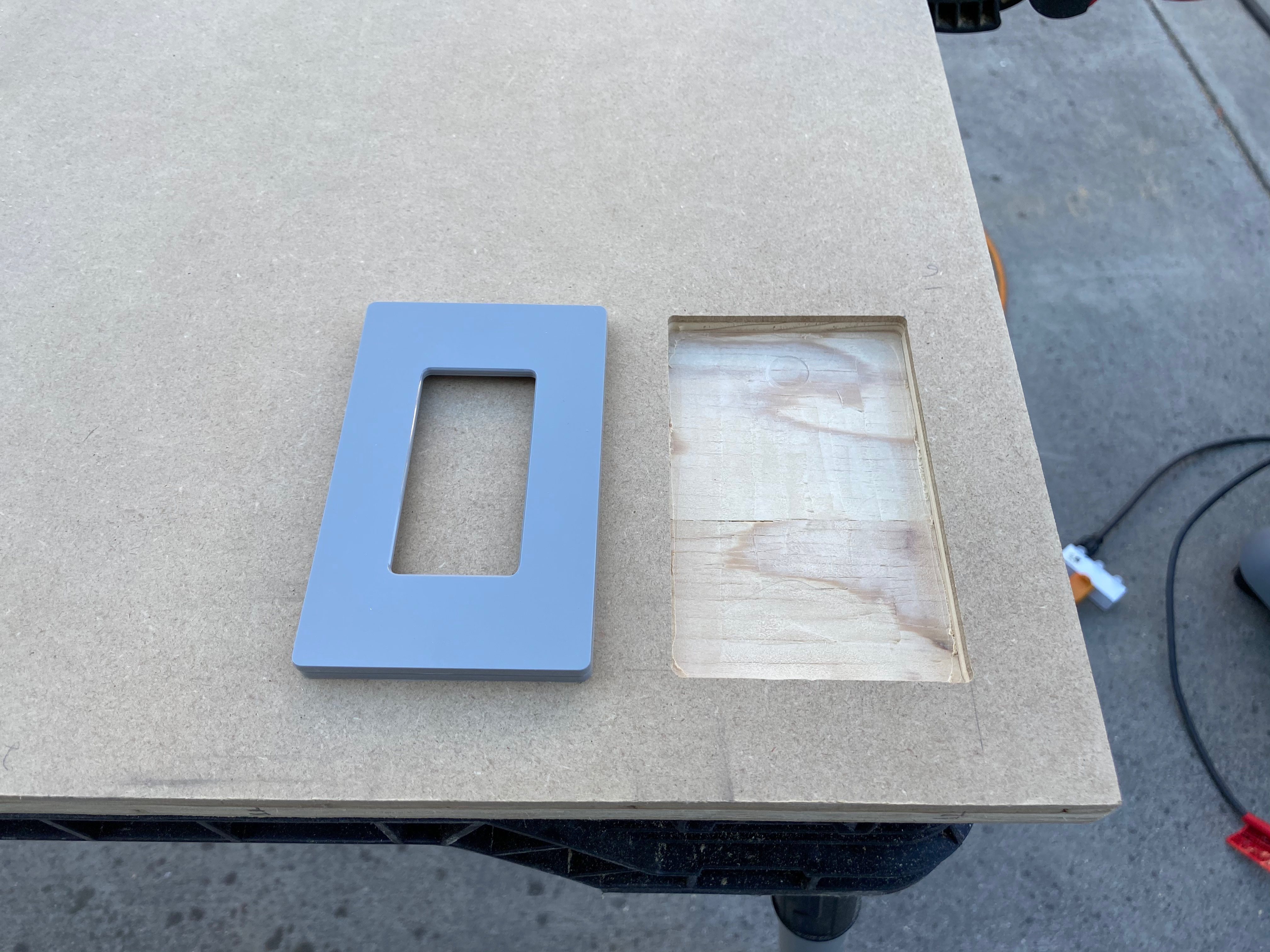
Next I used my router to carve out a recess for the power switch face plate on the right side piece:
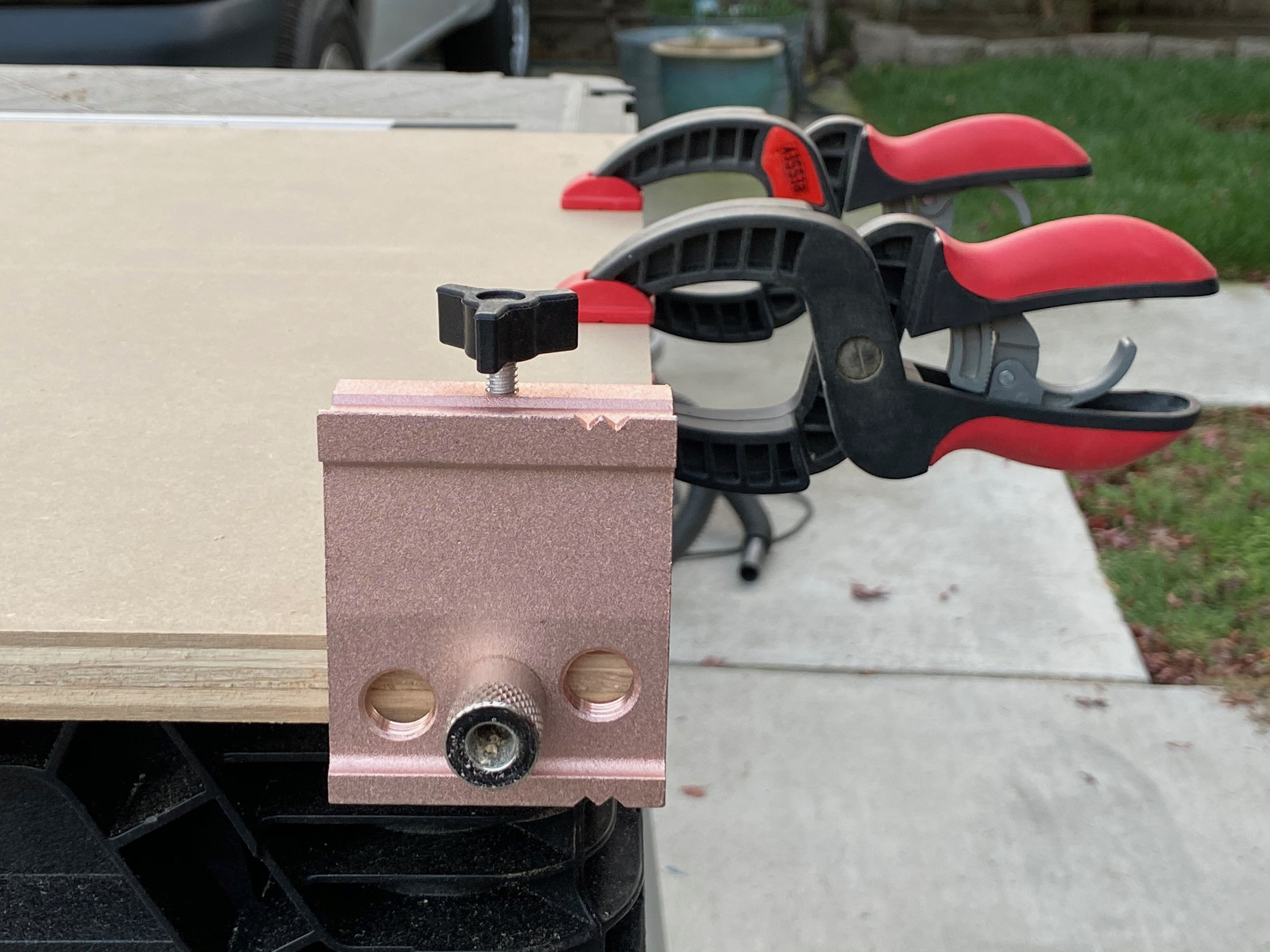
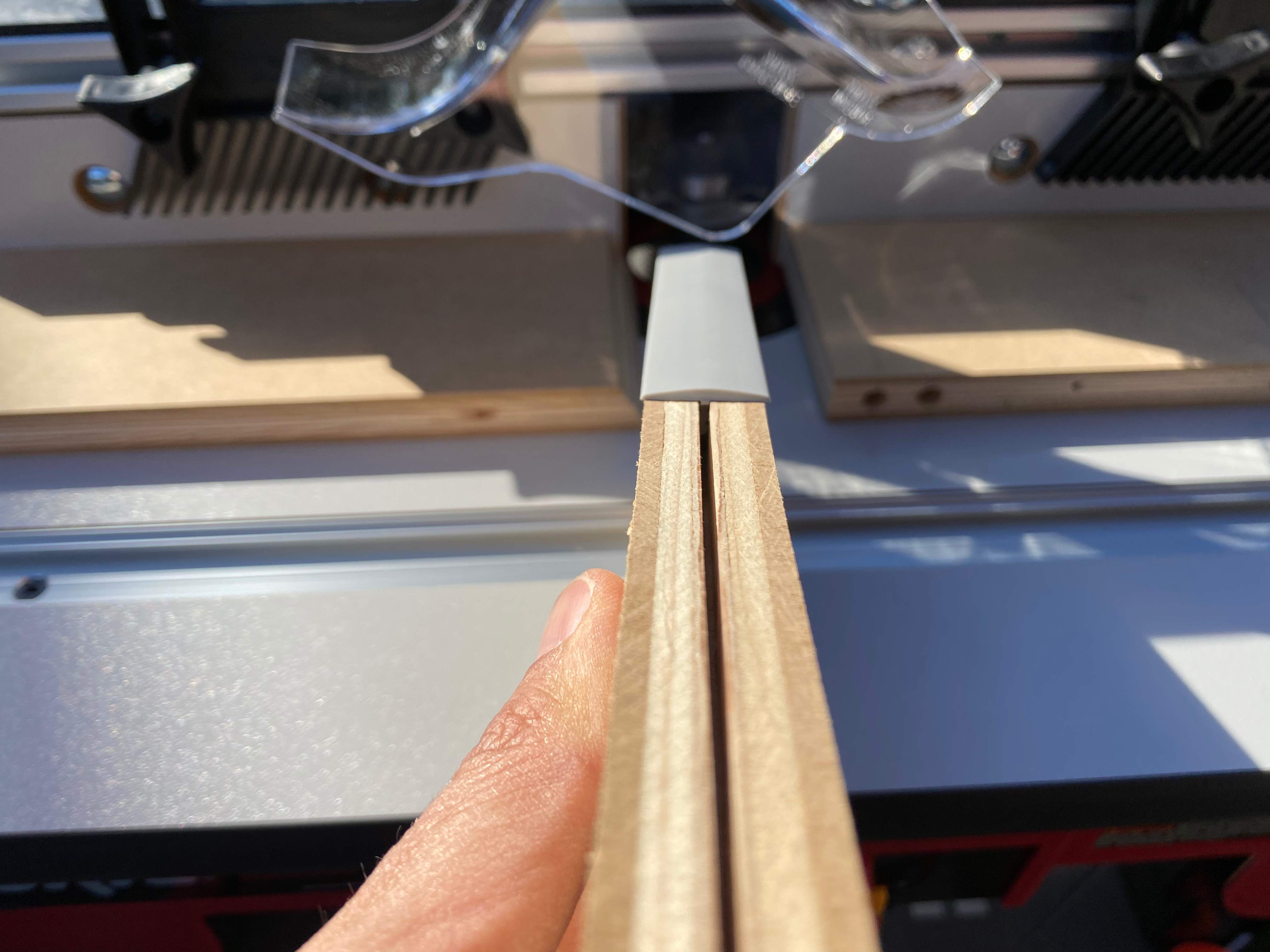
I also used the router to cut the groove on the edge of the boards that will get T-molding. Here is a test piece done to dial in the position of the groove, with a small strip of the gray T-molding I will use installed:
In the photo above you can clearly see the different layers of the Jaycore, with plywood in the middle and MDF on both faces.
With the top, bottom, left and right pieces done, I then cut a smaller panel for the back that will have two exhaust fans – something like this:
They’re simply 120mm computer case fans but work well for other random application such as this one and are really quiet.
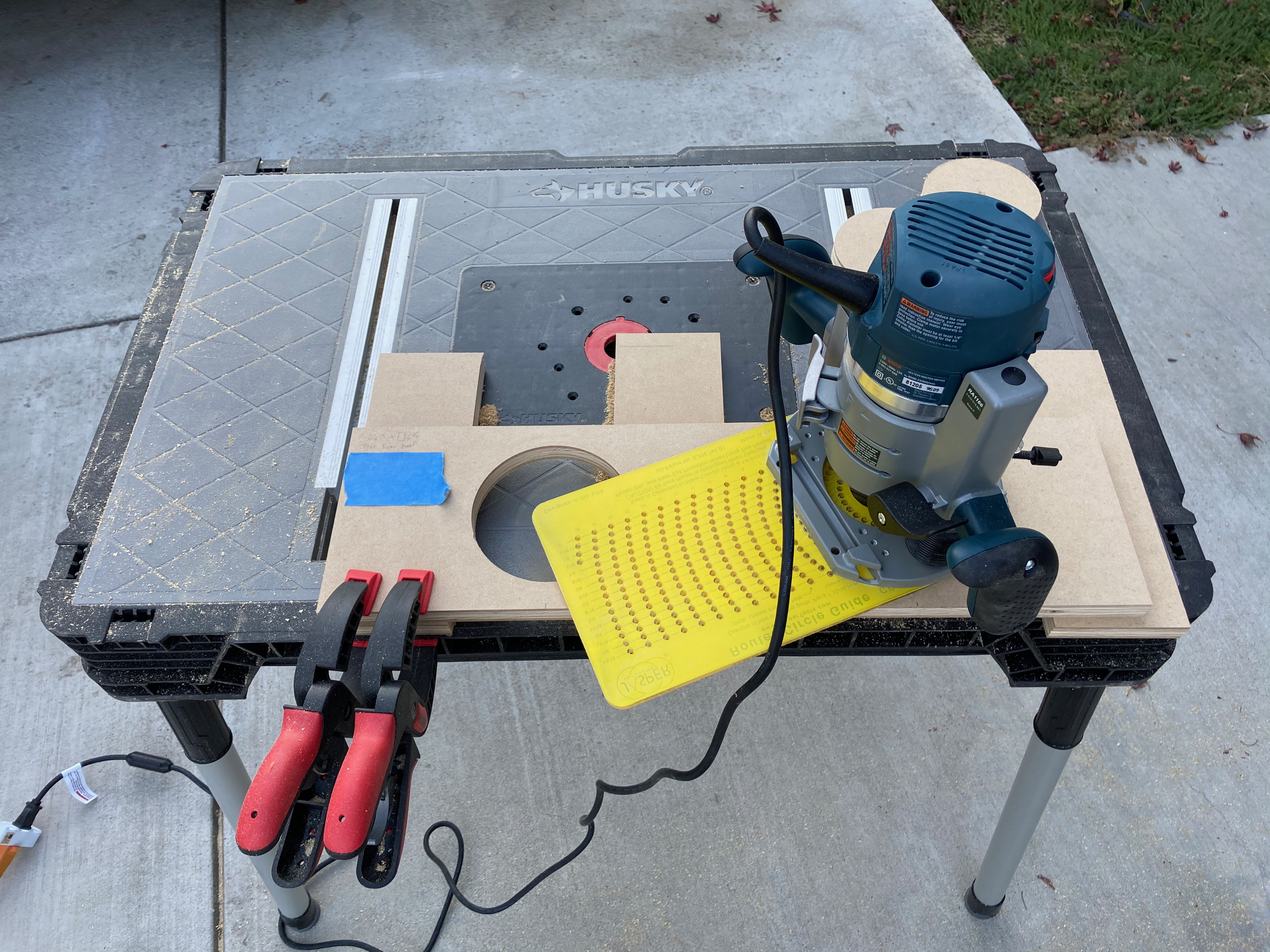
I then used a circle cutting jig on the router to cut the openings for the fans:
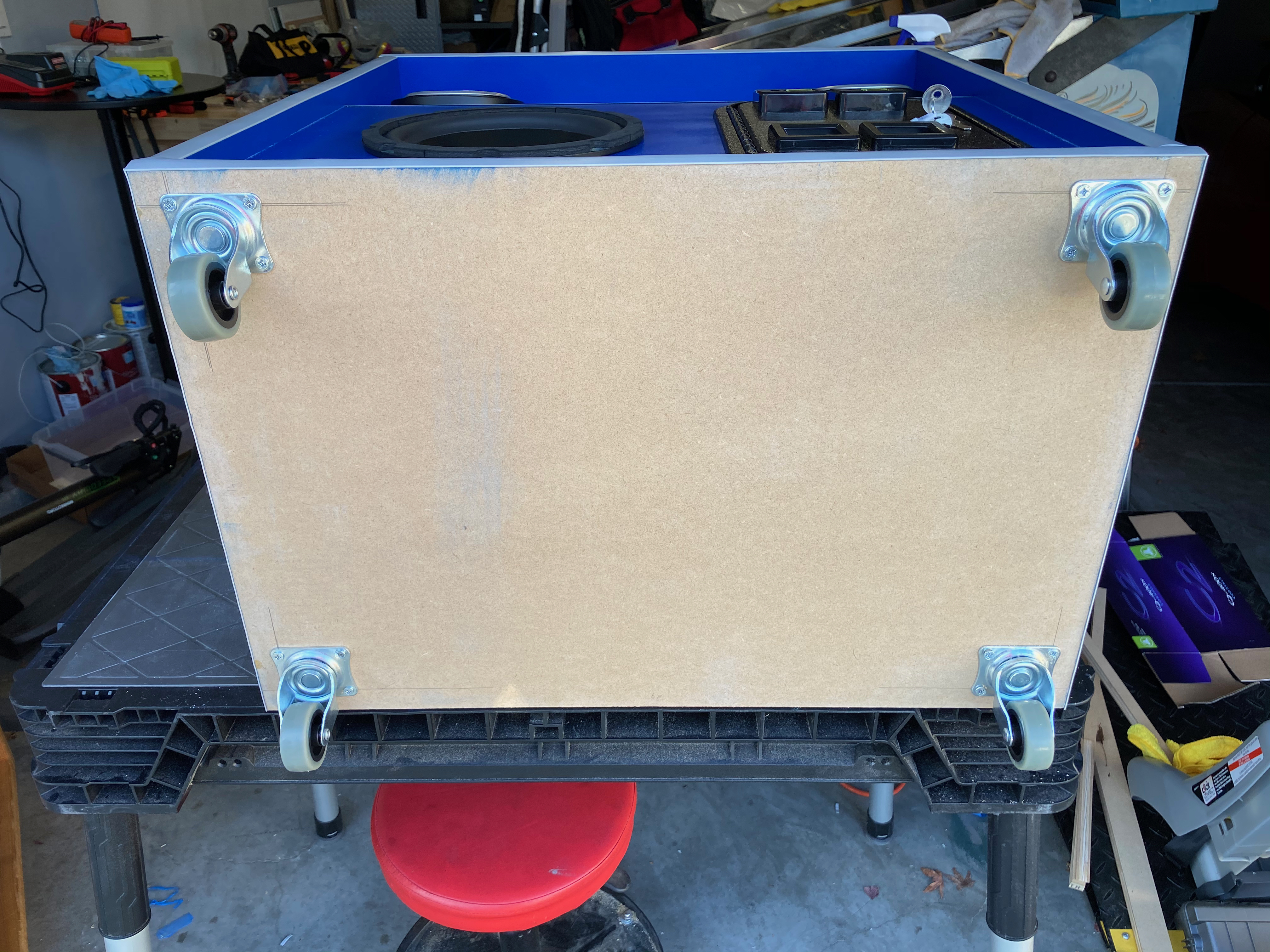
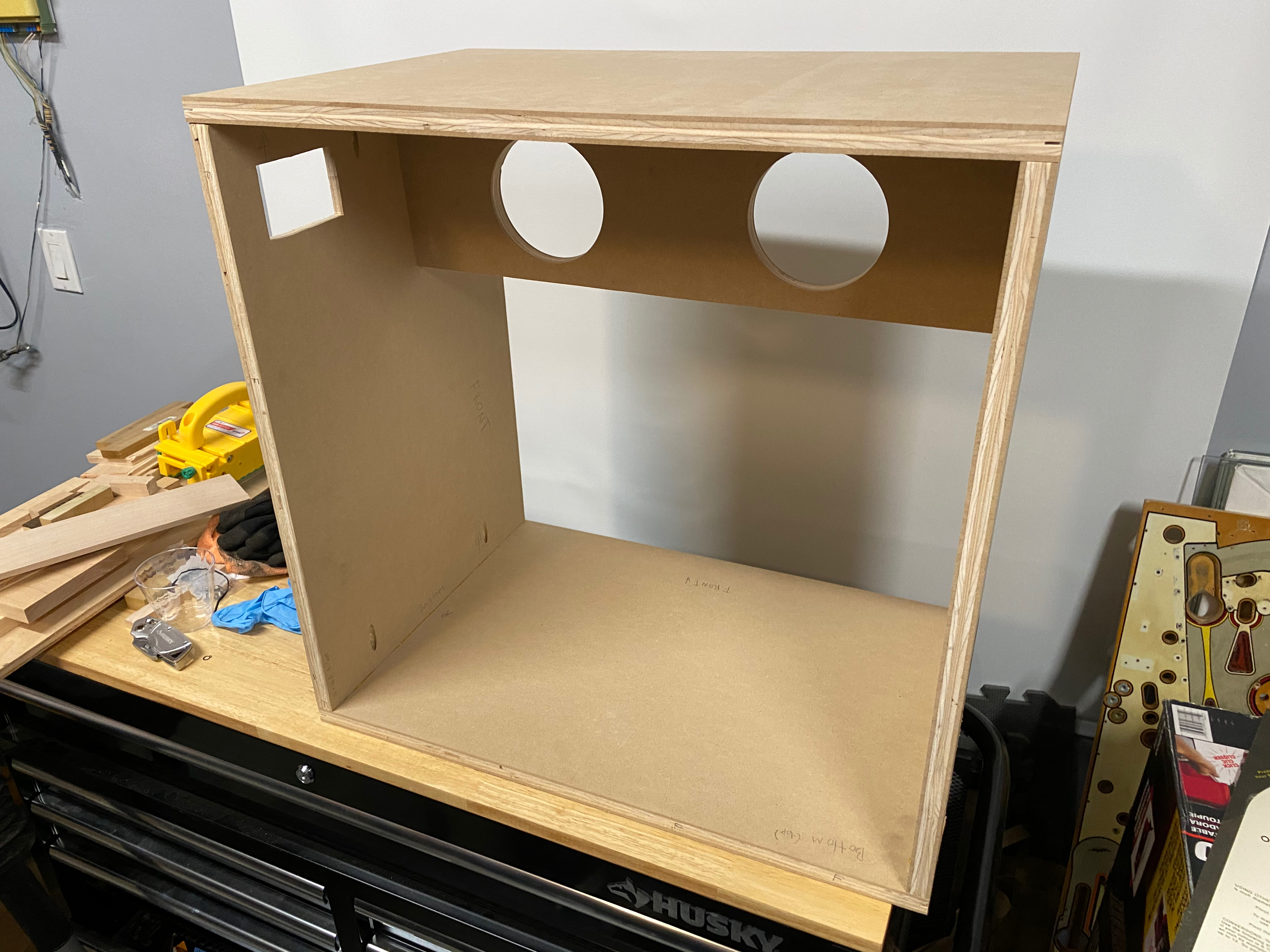
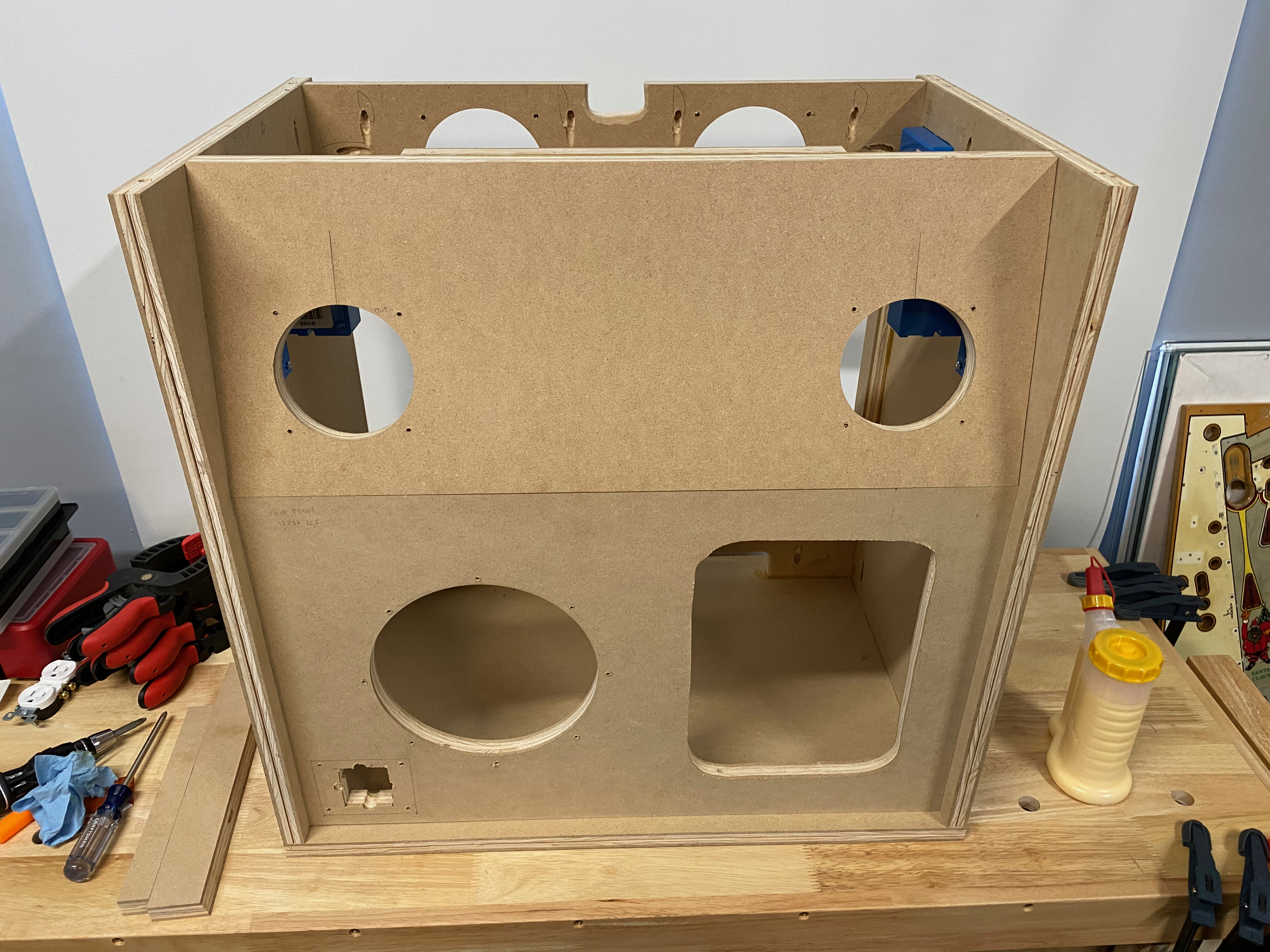
I now had enough pieces to assemble the basic box shape! I drilled pocket holes (not pictured) and put it together. It turned out pretty square and everything lined up well. Woo! I’m sure the experienced woodworkers are rolling their eyes here but this is the biggest woodworking project I’ve ever undertaken so forgive me while I pat myself on the back 😛
Also note my pocket holes are on the inside, pointed towards the outside – not as strong as the other way around. Some (Hi again Steve!) may consider it a no-no, but I did a test piece and given I’m also using dowels the joint ended up being plenty strong. Doing it this way saved me a ton of work filling the pockets that would be visible if I had done them on the outside.
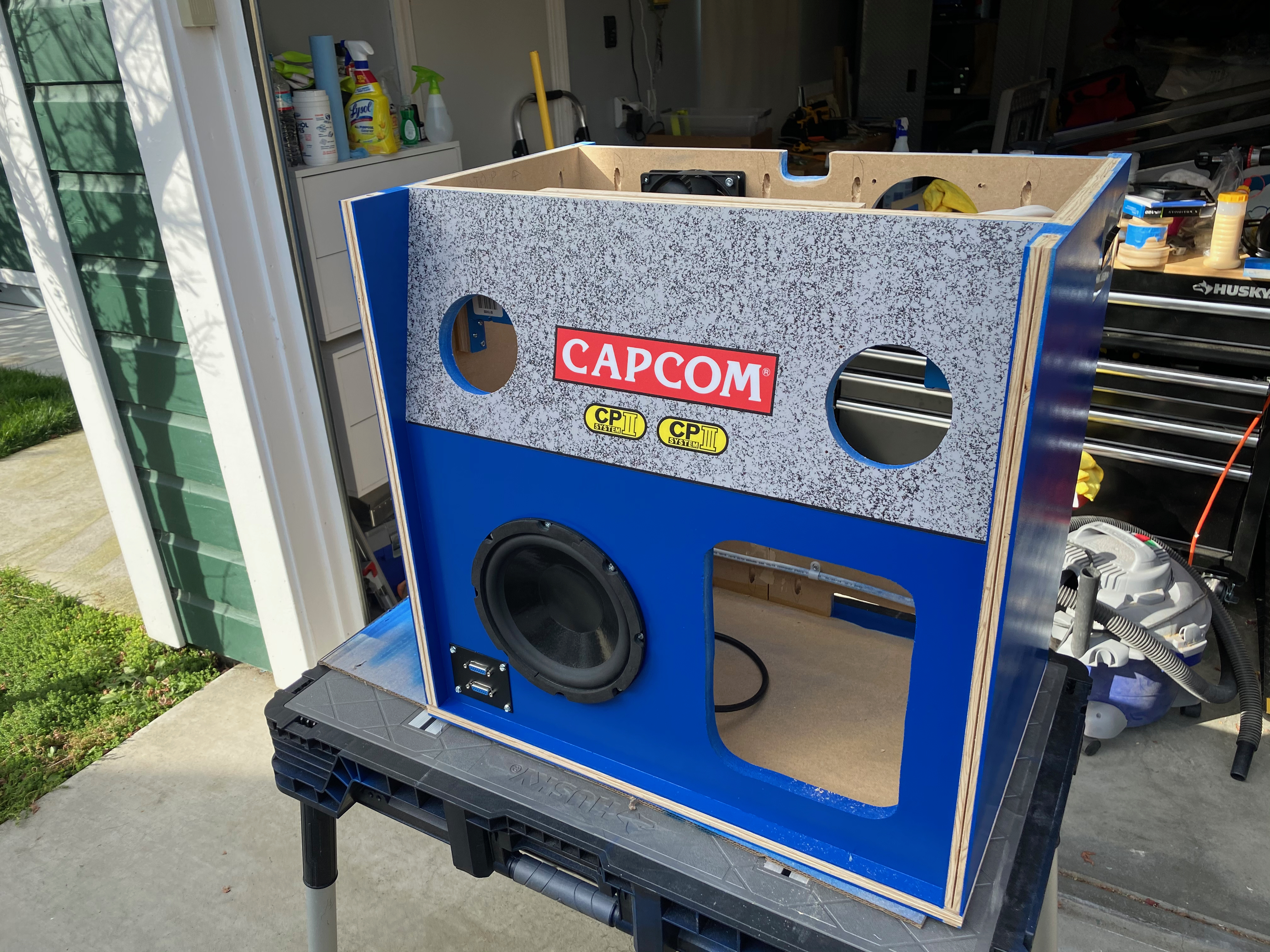
On to the front! I used a jigsaw for the coin door and DB-15 cutouts, and the woofer hole was cut in a similar fashion to the fan holes.
I then created the top speaker panel. It’s construction was very similar to the fan panel, except two of the edges were beveled 15° – this was my first time using the bevel feature on my table saw! A few pocket holes and a reinforcing piece between the two and voilà, my box has a front now.
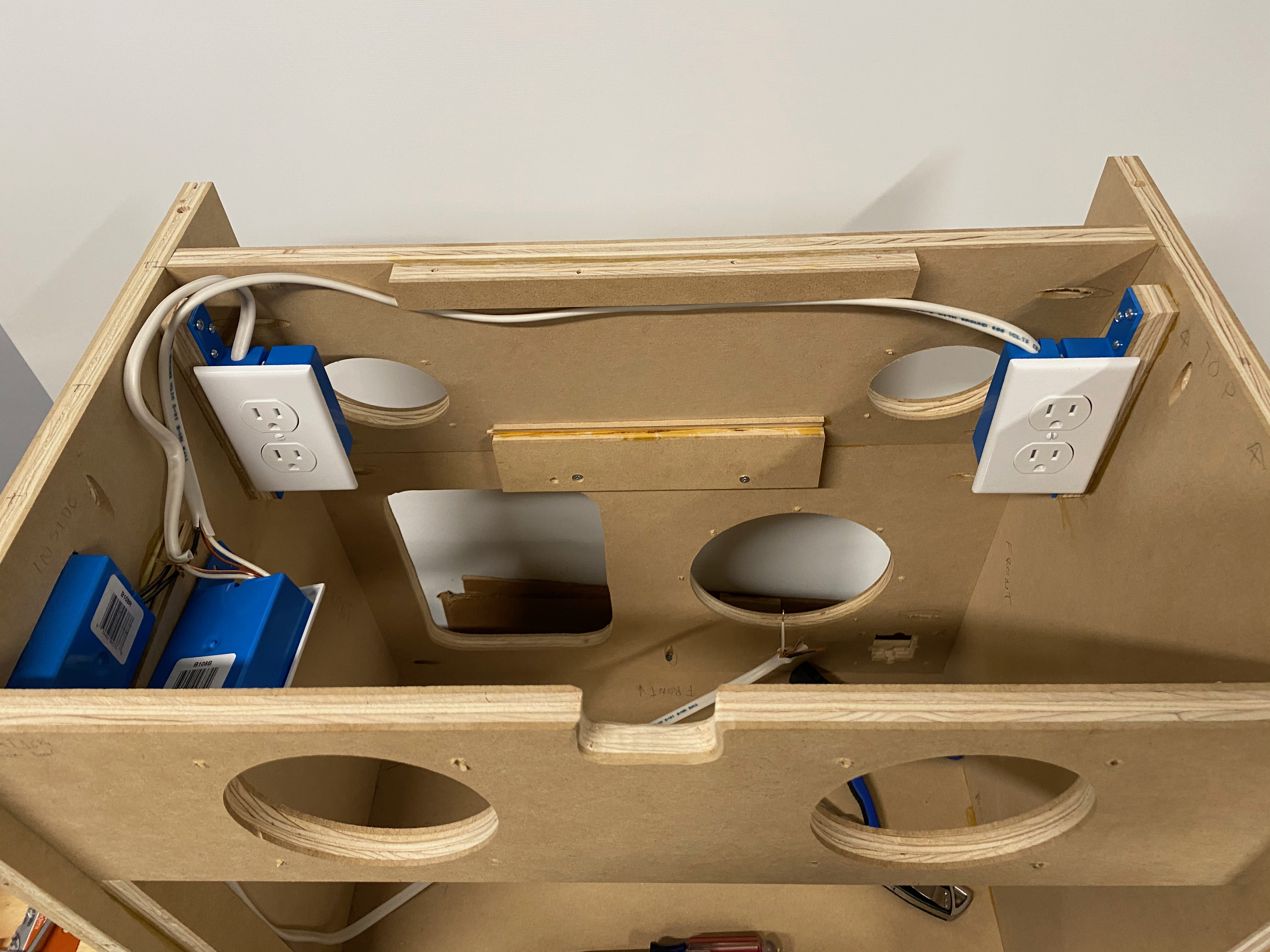
Although most of the interior wiring and kitting out will be done after paint, I decided to do the 120V now to avoid damaging the finish later. My cabinet is wired with two separate 120V circuits via a dual switch, such that I can turn on and off the power to the sound system and arcade boards separately. This makes it possible to use the Superbench as a sound system only, useful for playing game consoles.
You’ll also notice the small cutout between the two fan holes – this is to allow the passage of video cables from inside the bench up to the TV.
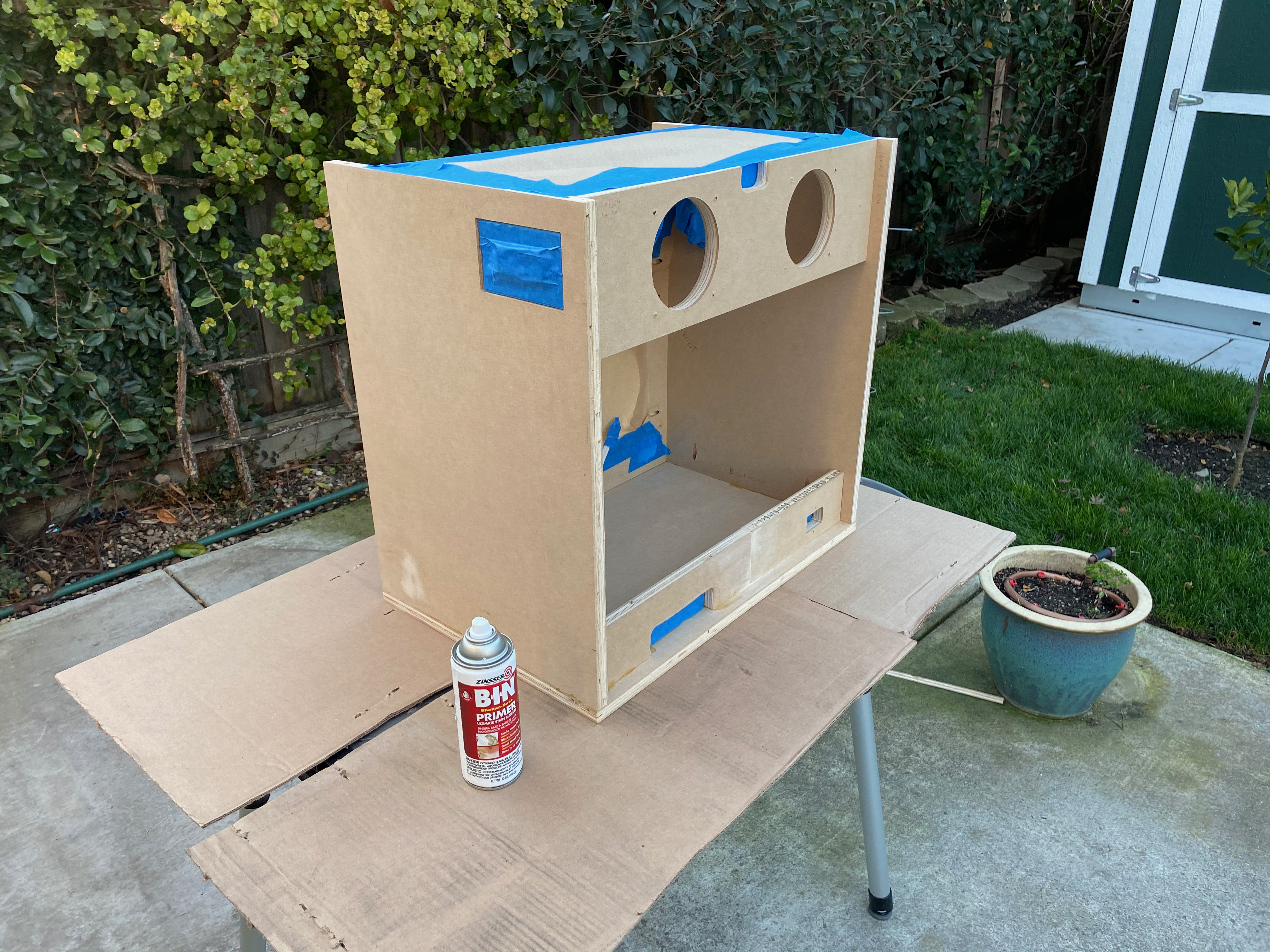
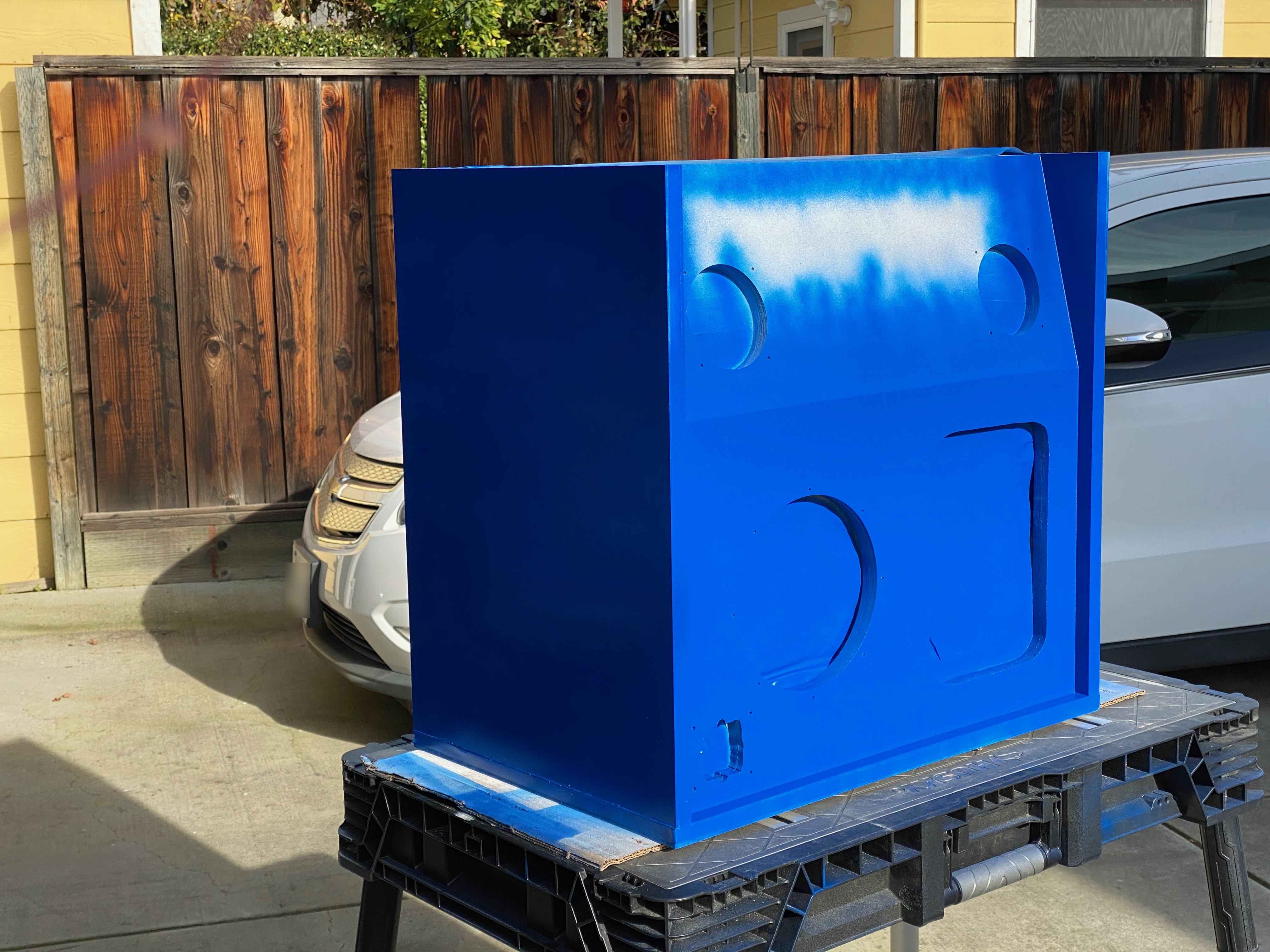
Finally, on to paint! If you’ve never painted MDF before, you’ll find that it soaks up paint like a sponge – this makes it very very difficult to get a good finish. I did some research online and found a product called Zinnser BIN which is supposed to seal the MDF, leading to much better results. I did a small test piece first and it seemed to work, so off I went!
My back yard is not just my wood shop – it’s my spray booth, too! 😬 Dust can be a real problem painting outdoors like this but I’ve found as long as it’s not too windy and the surfaces are all vertical you can still get good results – forget about it with horizontal pieces though, the wet paint will catch every little piece of dust falling from the air. Notice the top piece isn’t on in the photo above and will be painted separately.
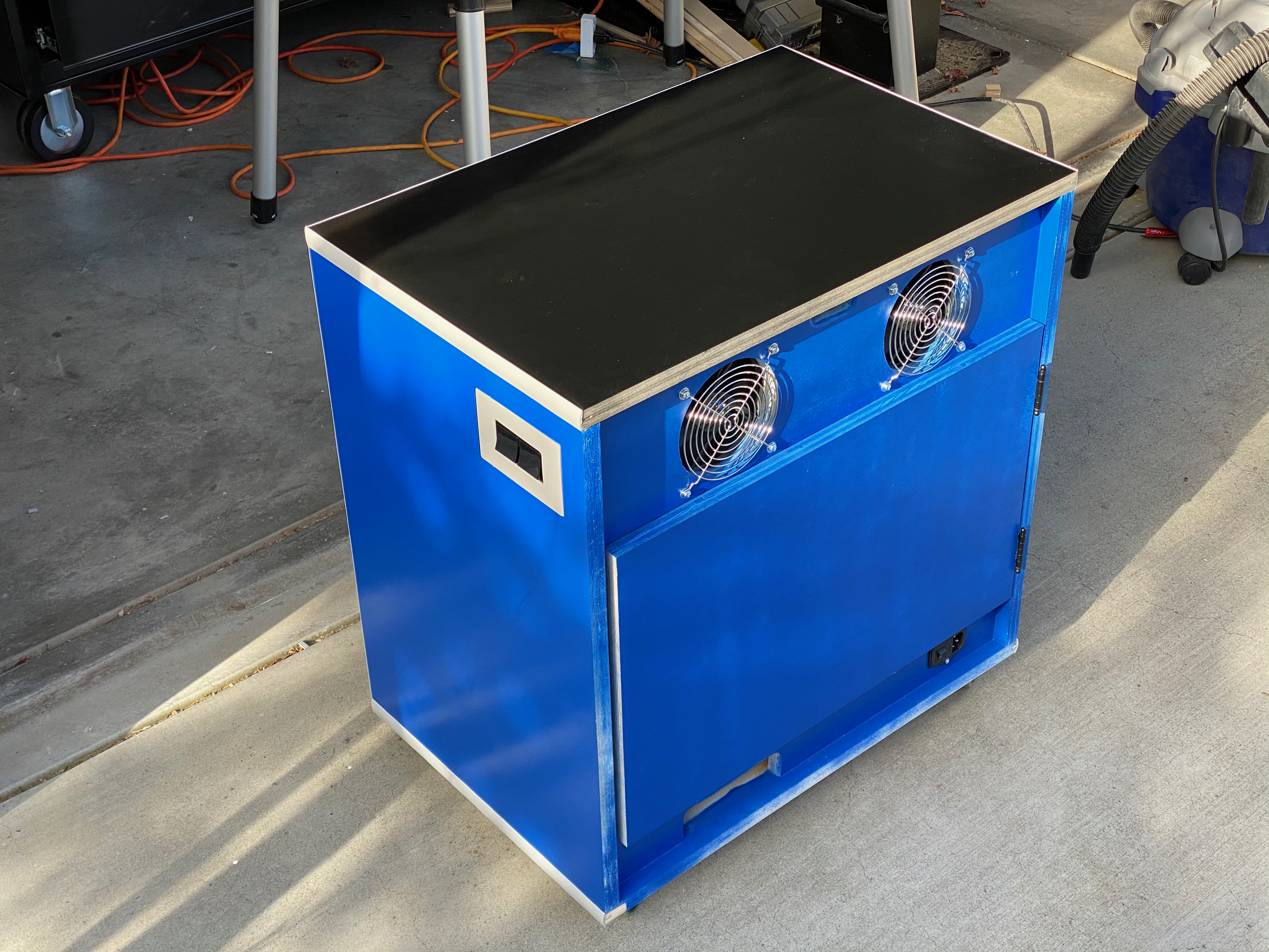
A few coats of Zinnser BIN done, with the top piece leaning on the fence in the background. I then sanded it very lightly to smooth out the finish, and moved on to paint. I used “Gloss Deep Blue” by Rustoleum Painter’s Touch 2x. The finish came out pretty nice! Note I didn’t have to worry about the edges of the boards as those will be covered in plastic T-molding.
That’s it for now! Stay tuned for the exciting conclusion in Part 2 in which I will finish the project out with interior wiring, sound, artwork, and trimmings!