Preparing to wire flippers

I spent some time tonight getting more familiar with all of the various circuits from the Doctor Who wiring schematics pages. Suffice it to say, the manual and its schematics are priceless when you have a machine completely un-wired πŸ™‚Β Then it was on to prepare the wiring harnesses for the flippers on AB1. Thankfully I can simply re-use the harnesses from Doctor Who, at least for the flippers!

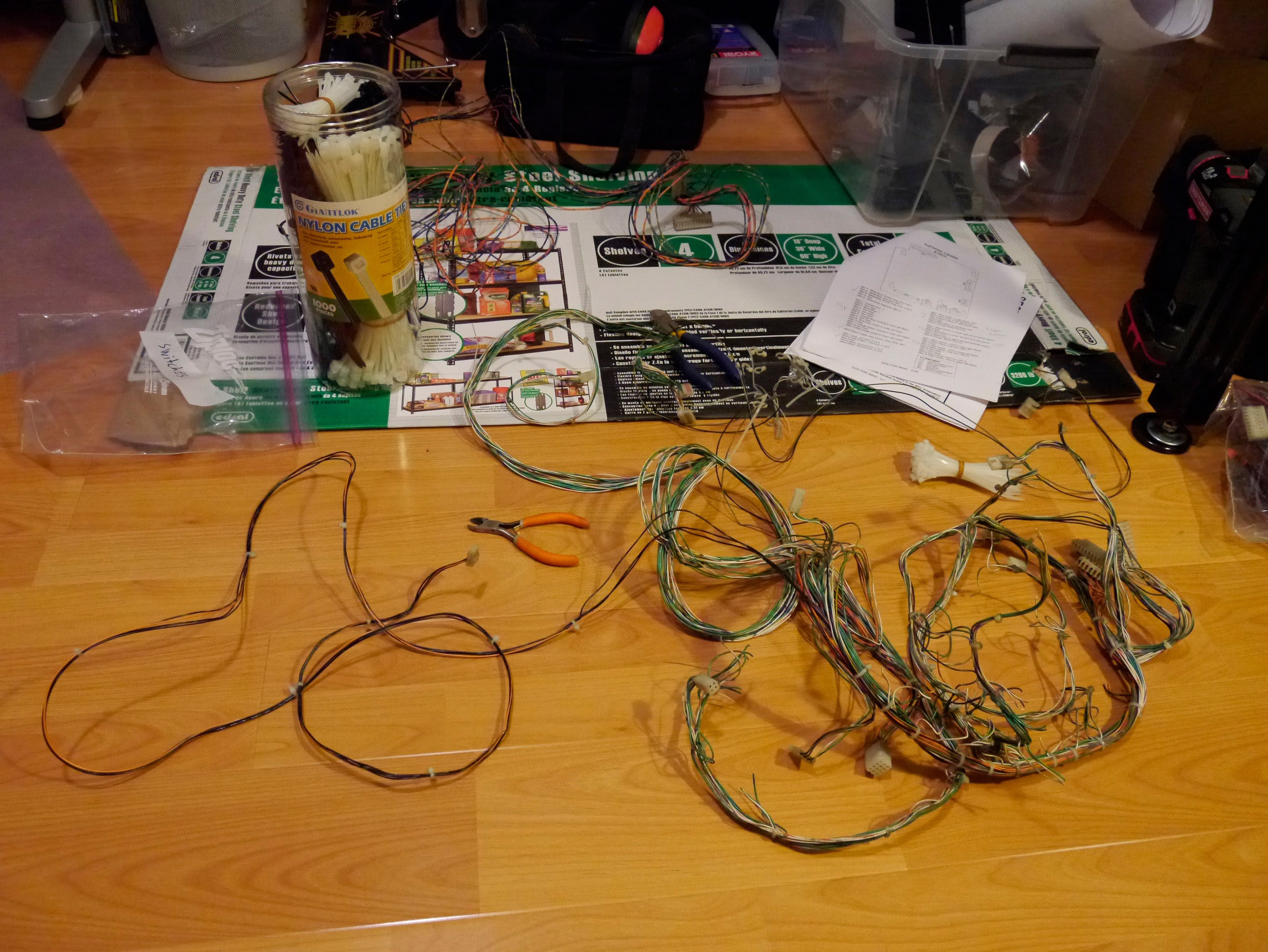
During disassembly of Doctor Who, it became pretty clear that its wiring harness was Β nicely separated into different bundles by function – one bundle for lights, another for switches and a third for solenoids. Since the flipper solenoids use dedicated wires, it was pretty trivial to separate them out to re-use as-is. The End-Of-Stroke switch wires however were a different story! Even though they are dedicated wires to the circuit and not part of the switch matrix, during manufacturing they were nevertheless bundled together with zip ties with the rest of the switch matrix wires. It was still relatively painless to separate them out – just some zip-ties to cut and then replace once the wires were separated out. Here’s a photo where I am about halfway done. The EOS wiring harness is on the left, and the big jumble of green wires on the right is for the switch matrix.Β I can already tell the Costco zip-tie mega pack is going to come in handy on this project πŸ™‚

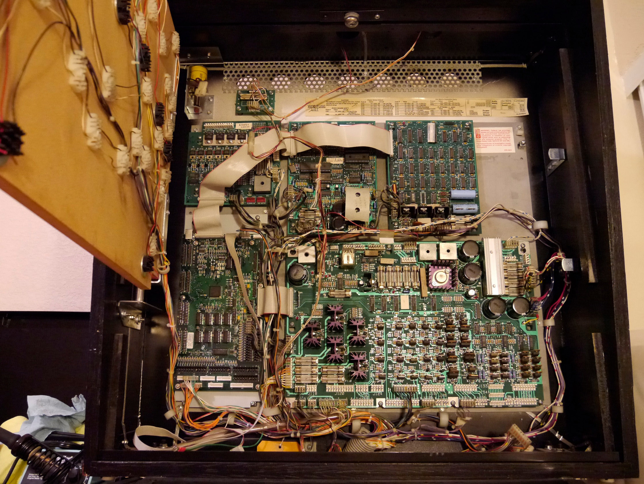
Finally, I spent some time re-connecting all the cabinet wiring to the boards in the backbox. Even with the Doctor Who playfield gone, there are plenty of things to hook up here: the flipper button and other cabinet switches, transformer power, DMD and Fliptronics boards, lights for the backbox and cabinet, etc.

Next time I should be ready to actually wire up the flippers and see if I can play a ball on my blank playfield!

Posted in Alpha Bravo One | Tagged , , | Leave a comment

Started playfield assembly

Today I started assembly of the basic mechanisms on my custom pinball playfield! It was super exciting to install the hinge brackets and drop the empty playfield into the cabinet for the first time πŸ™‚ In addition, the following assemblies are coming along nicely:

  • Ball Through/Feeder/Shooter
  • Flippers
  • Kickers

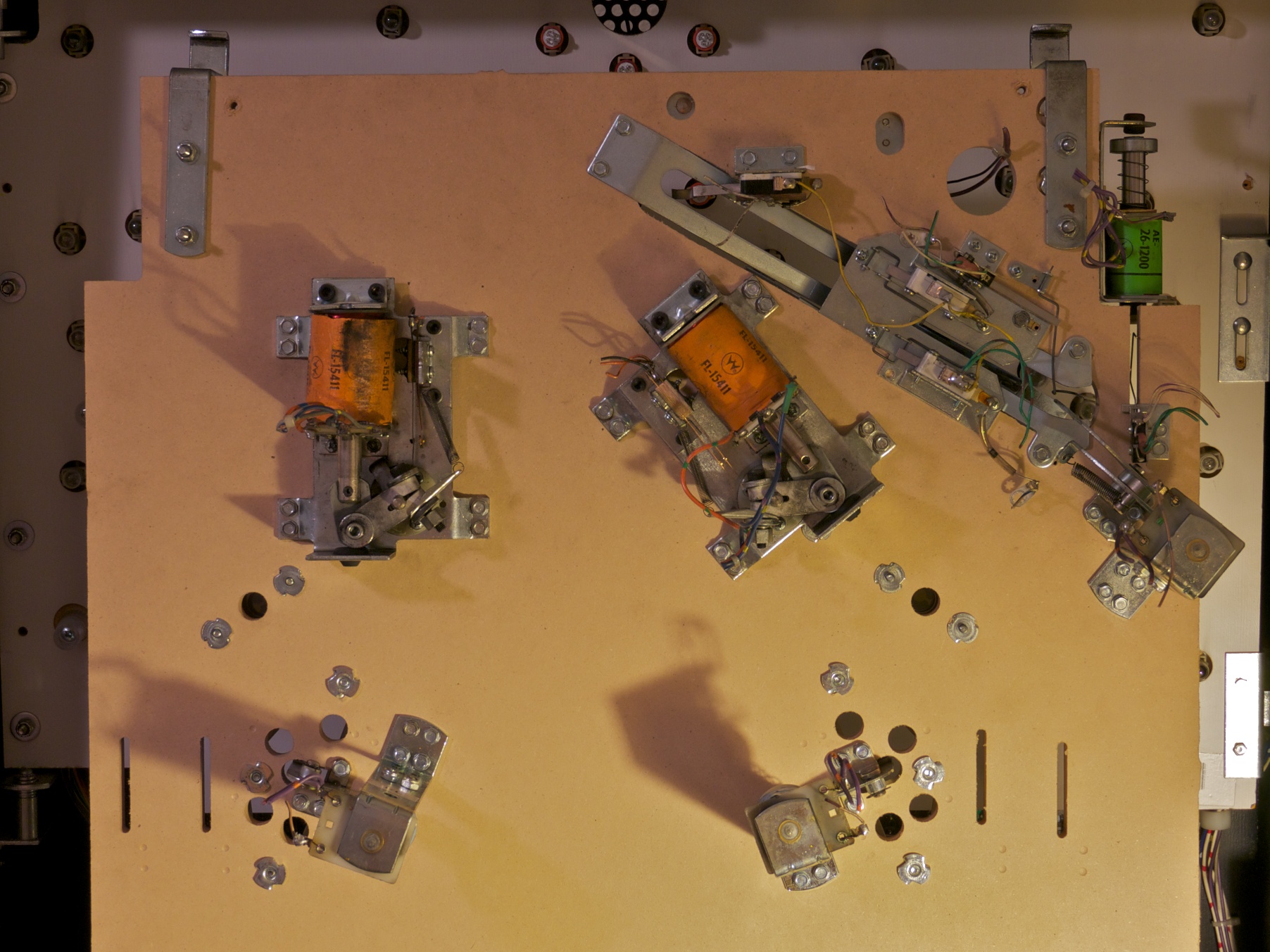
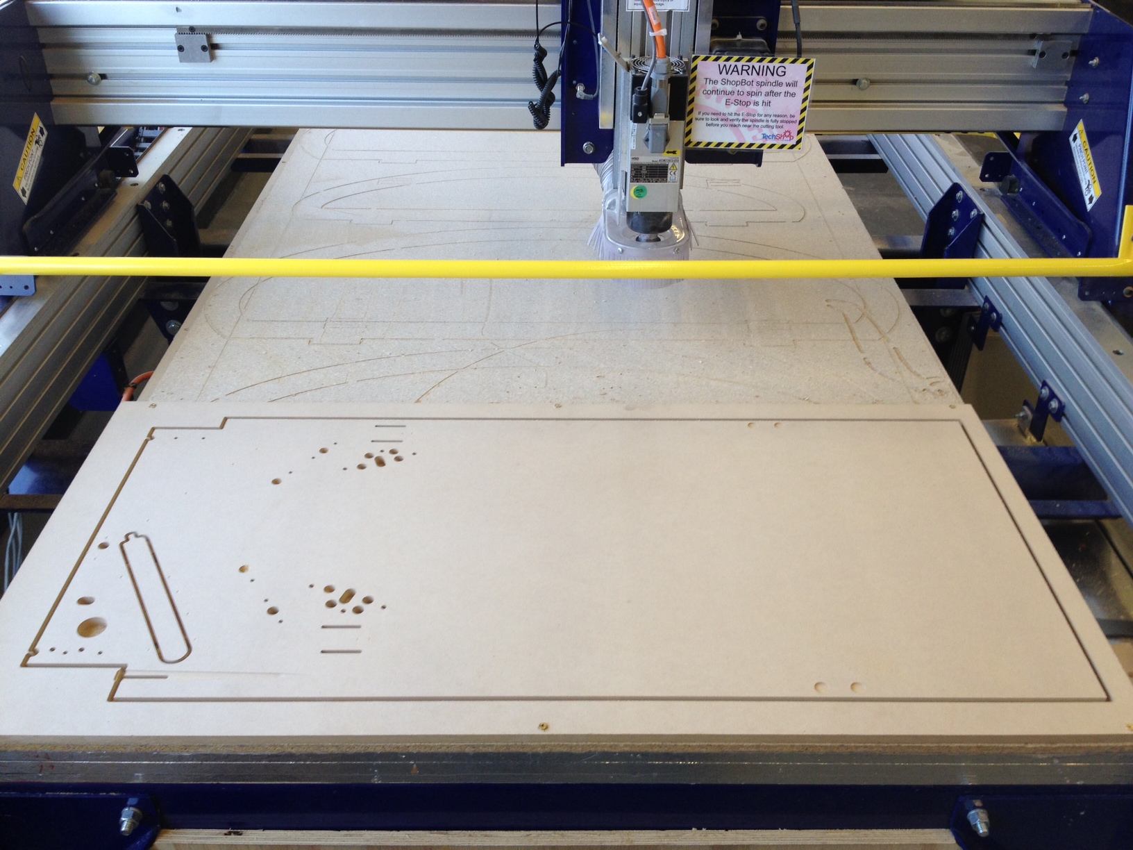
I couldn’t wait to find out how well I did with the CAD file in placing the holes for all this. In the end, almost everything came out just right except for a few minor elements here and there – certainly nothing critical that warrants another trip to the shopbot, at least for now πŸ™‚ It was pretty trivial to take note of what needs to move, so fixing the CAD file will be a piece of cake and the next playfield prototype should be perfect! Here’s the top of the playfield now:

One thing took me by surprise however – how tricky it is to get the kicker and ball feeder mechanisms to line up just right. Unfortunately these Williams mechs are each comprised of two completely separate brackets that need to be individually screwed to the playfield. The position of each bracket relative to each other isΒ critical to ensure proper unrestricted movement of the mechanism. You can see what I mean in the underside view:

One could wonder why everything isn’t on one single bracket, like the flippers… for cost savings perhaps? Or to allow more freedom in choosing the location of the bracket that holds the coil? It’s too bad, one bracket would make assembly much more quick and painless. Regardless,Β I will have to improve my CAD drawing to get these measurements just right for the next iteration of the playfield. Using these Williams mechs is still way less painful than designing and building my own! πŸ™‚

Next up, more playfield assembly! Also, I have to start thinking about how to wire everything back up to the backbox!

Posted in Alpha Bravo One | Tagged , , | 1 Comment

Fabricated blank pinball playfield!

If you’ve been following along on the blog, it may look like I haven’t made any progress in a while… Well, I have πŸ™‚

It turns out fabricating things like pinball playfields is pretty tough with tools you typically have at home. You almost certainly could, but cutting the many holes in a playfield requires precision – it would be extremely time consuming to do it all by hand. Plus, if during the design of the game you decide to move the position of a single hole, well, back to square one cutting everything all over again.

Clearly, CNC tools can do it better. Luckily for me, there is a place near where I live that has all sorts of expensive tools including CNC machines that I can use. It’s called the TechShop! For making my playfield, they have a ShopBot CNC router that is perfect for this sort of thing. I’ve spent the last few months taking various CNC classes at the TechShop, and finally today I was able to make progress on the custom pinball machine.

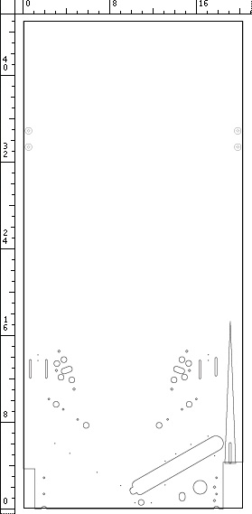
For my “blank” playfield, my plan was to include everything needed to install the playfield into the machine with basic playfield parts: Flippers, kickers, inlane/outlane divider, and the ball through / feeder / shooter. I drew the holes I was going to cut in CorelDRAW and Adobe Illustrator. In the end my CAD file looked sort of like this:

As you can see, there’s not much near the top of the playfield, with the exception of the holes for the hinge bracket bolts. The CAD file includes vectors which are used for a few different types of elements:

  • The outline of the playfield
  • Holes and slots to be cut all the way through the playfield
  • Pockets cut at a certain depth (to allow flush mounting of T-nuts for instance)
  • The V shaped groove for the shooter lane
  • Small dimples for drilling pilot holes

After I was done drawing everything, and making sure the dimensions were all correct, I imported the drawing into CAD to CAM software called VCarve Pro. This software is used to generate CNC toolpaths from your drawing – that is, taking a drawing, and transforming it into commands that will control the router bit such that it will make a blank piece of material into what you drew on the computer! Tool cool. It is then just a matter of running the program on the ShopBot!
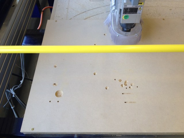
In the photo above, the ShopBot has started cutting the holes in my design. I used a 3/16″ downcut square end mill for these particular holes. Some of the other elements used different tools, such as a 1/4″ square end mill, and a 1/4″ ball nose end mill. As for the material, I’m using MDF here but only because this is a prototype piece and I’m sure I will iterate on the design. MDF is cheap, easily available, and straight and true. For the final piece I will use 9-ply maple veneered plywood, which is really nice but also expensive at 125$/sheet!

In this photo the features on the front side of the playfield are all finished. As you can see, the ball through still has a center discard piece that needs to be removed. It is held in place by tabs (which you add in the CAD to CAM software) whose purpose are to prevent that discard piece from flying all over the place as the router finishes the cut. Similarly, the playfield itself is fixed to the outside ring around it by tabs. I cut the tabs using my handheld dremel tool, then flipped the playfield to do the features on the backside (mostly pilot hole dimples). At the 2011 Pinball Expo Stern factory tour, Gary Stern pointed out that you can’t build a pinball game without a pin press to put dimples in the playfield – that simply isn’t true, you can use a CNC router like I am doing here πŸ™‚

Finally, here is a zoomed in view on the lower portion of the finished product. The downcut tool made extremely clean cuts and I’m super happy with it! My shooter lane V-groove could be better, but I have a plan for that – going to try with a v-shaped bit next time.

The next step is to install this playfield into my cabinet, install flippers/kickers/etc on it, and then start playing with the layout of my ball guides, targets and ramps! I’m also going to take the vacuum forming class at the TechShop and see if I can make some decent ramps myself πŸ™‚

Posted in Alpha Bravo One | Tagged , , , , | 5 Comments

Installed P-ROC in Doctor Who

The P-ROC is a drop-in board that replaces the CPU board for pinballs. It connects to your computer and allows you to control the features (solenoids, lamps, DMD, etc) of the machine yourself. Williams WPC is supported (amongst others), which is what Doctor Who is. It turns out it is pretty trivial to install, which is great!

First, let’s look at Doctor Who before making any modifications. The main things to see here are the CPU board on the lower left (the one with the three Duracell AA batteries), and the power driver board on the lower right. Note as well that the DMD (not visible, below the power driver board) is connected to the PCB at the top right via a thin ribbon cable.

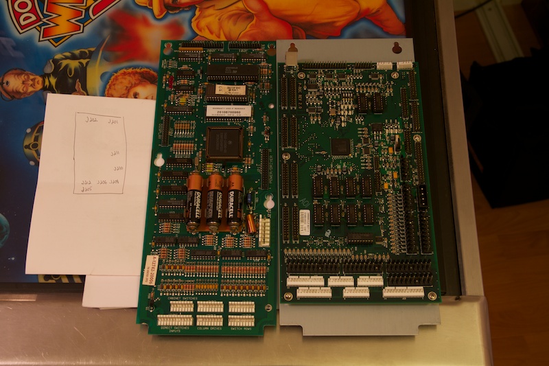
I took note of all connectors that were connected on the CPU board. These connectors will need to be transferred to the appropriate location on the P-ROC board. I then disconnected everything from the WPC CPU board, and pulled it from the machine. Here is the stock WPC CPU board (left) next to the P-ROC (right).

My P-ROC came on a mounting plate with holes in the exact same spot as the holes on the WPC CPU board, which makes it trivial to mount back into the backbox. As you can see by comparing the two boards above, the P-ROC has many more plugs for connectors than the WPC CPU board. This is because the P-ROC supports more than just WPC machines. Many plugs end up un-used on the P-ROC depending on which configuration you are using.

I then used the P-ROC connector mapping document to re-connect all the connectors that were originally going to the WPC CPU board to the appropriate P-ROC connector. One thing to take note here is that there are a couple connectors that originally did not connect to the WPC CPU board that need to be transferred to the P-ROC. These are the fliptronics connectors (originally going to the fliptronics board) and the DMD signal ribbon cable (originally going to the DMD driver board). Here is the backbox again with everything connected back up to the P-ROC:

Note now how the thin DMD ribbon cable is going up to the P-ROC board in the lower left. I double-checked that all the connectors were in the proper place, then powered on the machine to see what would happen. Success! The letters “P-ROC” appeared on the DMD display. Finally, I connected the P-ROC board to my computer via USB. At this point I was able to run the P-ROC test program and start playing with the C API. With this, I can write software to control all the solenoids and lamps, and read switch states! Very cool. It didn’t take long that I had a very simple program running that would feed me a new ball when pressing the “Start” button, shoot the ball when pressing the ball launcher, activate the Tardis popper when the ball triggered its opto. The pop bumpers all worked and the flippers too! πŸ™‚ Note: Just make sure when using the P-ROC test program that your sample YAML file is set to the proper type of machine (in my case, WPC).

Posted in Alpha Bravo One | Tagged , | 1 Comment