
Next up on the Space Shuttle playfield swap was tackling the pop bumpers. To do these, you need access to both the top and bottom of the playfield, so I was waiting until the playfield was back on the rotisserie to start on this job.
To build pop bumpers, you first start on the top-side. I’m using all new parts here – they’re inexpensive and will go along well with the shiny new playfield. The first five parts to go on here (seen below) are the pop bumper base, spring, skirt, body, and lamp holder.

Before moving on to the underside, here’s what the top side looks like with those five components assembled:

On the bottom side, the next order of business is getting the lamp leads soldered in while making sure they clear the pop bumper bracket. After that, the switch stack can be positioned properly and screwed in. It’s helpful to move the solenoid bracket out of the way for access to those components:

Notice how dirty the spoon is on the switch stack! Next time I’m rebuilding pop bumpers, I’ll definitely order replacements for those as well. I soldered in the leads without difficulty and positioned the switch stack such that the spoon was centered as much as possible on the rod coming down from the skirt. As the skirt leans to one side (and hence the rod) when the ball rolls onto it, it pushes up on the spoon which closes the switch. For this to work correctly, the spoon has to be positioned just right over the rod. Notice that the holes on the switch mounting bracket (copper-colored above) are much larger than the #6 screw diameter. This allows for fine adjustments to the switch stack position after the holes have been drilled.
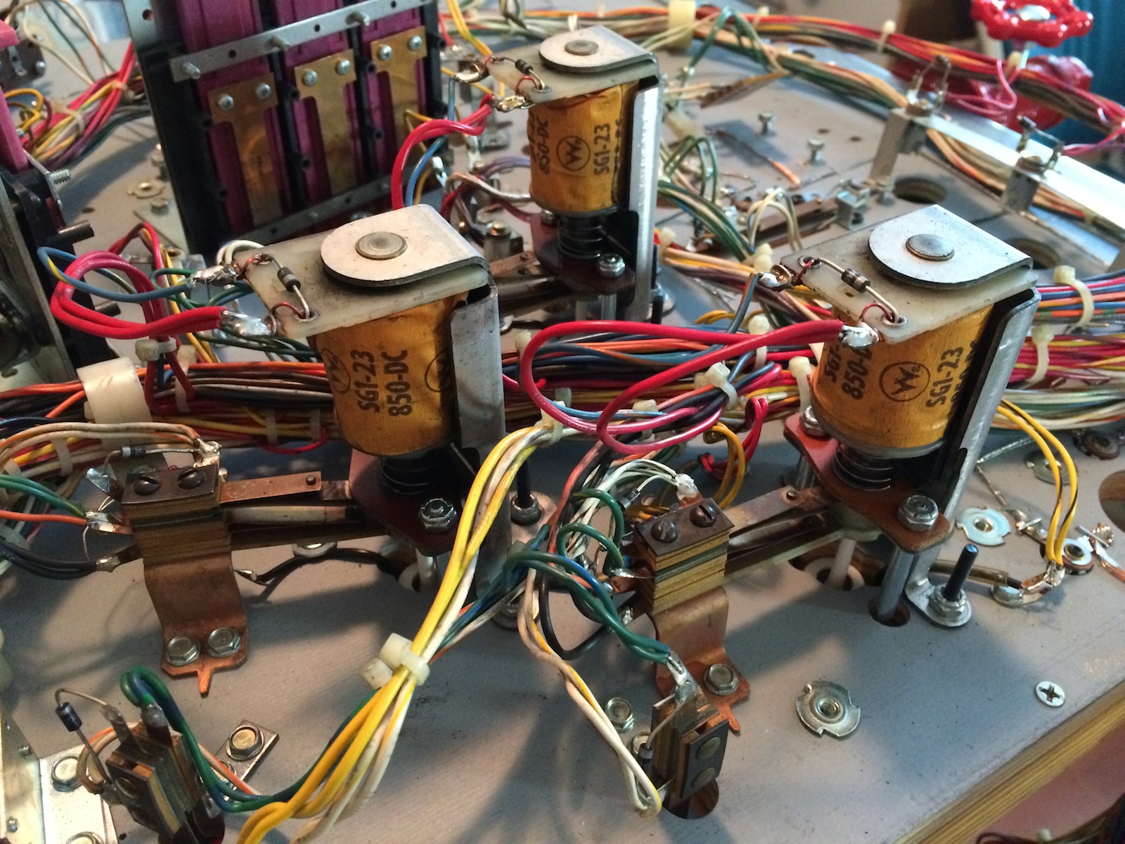
Finally, after the leads are all soldered and the switch stacks positioned, the ring-and-rods can be installed from the top side and bolted on to the solenoid yokes. Here’s a photo of the three completed pop bumpers from the underside:
And from the topside:

The pop bumper caps are still missing here obviously – they will get installed later as the rest of the top side plastics get installed.
